
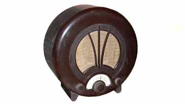
EKCO AD75 Vintage Round Radio
The AD75 was one of the iconic series of ART DECO round radio receivers produced by the EKCO company and now is a well sought after vintage or antique radio.
EKCO Radios Includes:
EKCO round radio series
EKCO AD36
EKCO AD65
EKCO A22
EKCO AD75
Iconic radio receivers:
Summary of iconic radio receivers
Radio receiver history
Crystal radio sets
Development of the superhet radio
Radio history / timeline
The EKCO company, named after E K Cole, its founder produced a series of classic radios of which the AD75 was one.
Initially launched in January 1940, production ceased during WW2 and the design was relaunched in October 1946 after the war had finished.
The AD75 radio was a basic single superheterodyne design that served well when it was launched and later when it was relaunched, offering style and sufficient performance for average entertainment listening.
The EKCO AD75 used a total of four valves to provide all the functions required, and one of the valves served as a rectifier so only three were used in the actual radio elements of the set.
Today all the Art Deco EKCO round radios fetch a significant premium when they reach the collectors markets. The AD75 is no exception and they reach prices several times that of other radios of their time.
Not only are these antique radios stylish, but they are also relatively compact and can fit easily within a modern room and this makes them very desirable as vintage radios.
AD75 radio controls
RTe AD75 vintage radio has very few controls, making it very easy to operate. There is the volume control, the tuning and waveband switches. There is also an on/off switch
The waveband switch is a rotary switch controlling all the RF tuning adjustments needed to change the radio between the long and medium wave bands. It is located on the left hand side of the front panel - when looking at it from the front. In the counterclockwise position it is on the medium wave band.
The tuning control is located in the centre and it controls the twin gang tuning capacitor needed for adjusting the local oscillator and RF stages. The two capacitor sections are mechanically linked, and part of the same assembly so that they tune at the same rate.
Above the tuning control is the main dial. There is also an assembly using cord to link the tuning capacitor to the dial so that the station required can be easily selected by moving to the required section on the dial.
The volume control adjusted the input to the final pentode giving the volume required.
At the rear of the radio is the power input connector. There is also a fuse which is a 1 ¼ inch 500mA variety.
The on / off switch which switches both sides of the power input is a dual pole toggle switch and this is normally mounted on the side of the radio.
Although not a control, the loudspeaker occupies the major space on the front panel, and this enables the audio to be unhindered in reaching the listener.
Basic AD75 specifications summary
The EKCO AD75 provided a basic specification for a broadcast radio, but this was more than sufficient for the needs of most listeners. The main attraction for these radios was the Art Deco styling.
| Brief Specification for the EKCO AD75 Vintage Radio |
|
|---|---|
| Parameter | Specification |
| Basic description | Superheterodyne broadcast radio receiver in Bakelite Art Deco case. |
| Manufacturer | EKCO, E K Cole Ltd, Southend-on-Sea, UK |
| Start of manufacture | January 1940, relaunched October 1946 |
| Valves (Tubes) | CCH35, EF39, CBL31, CY31 |
| Type of radio | Superheterodyne (single conversion) |
| Intermediate frequency | 480 kc/s |
| Receiver coverage | Medium wave and long wave bands |
| Power | AC: 200 - 250V at 40 - 100c/s DC: 200 - 250V DC |
| Case | Bakelite: designed by Wells Coates |
| Dimensions | 14 x 14.4 x 6.7 inches (355 x 365 x 170 mm) - (width, height, depth) |
| Original cost | £7 7s 0d at launch, increased to £7 17s 0d in July 1940 and then £11 11s 0d plus £2 9s 8d purchase tax when relaunched in October 1946 |
Launch and re-launch
the AD75 was initially launched in January of 1940, but with WW2 requiring all production be focussed upon war requirements, production appeared to cease for the duration.
The radio was relaunched with a few circuit modifications and under the same type number in October 1946. At this stage the price including tax was almost double what it was when it was first launched.
The circuit differences amount mainly to the addition of a few resistors and capacitors and a number of value changes. These did not materially affect the overall operation or specification of the radio.
EKCO AD75 circuit description
The EKCO AD75 used a total of four valves - three for the radio and one as a power rectifier.
The overall circuit is relatively straightforward and is a single conversion superheterodyne radio covering the long and medium wave bands, having an IF of 480kc/s.
Great care must be exercised when repairing these radios - even taking the back off the radio must be undertaken with care.
The four valves in the radio have different functions as described in the table below.
| Valve Line-up for EKCO AD65 Radio Receiver Circuit |
||
|---|---|---|
| Valve Number | Type | Use within the circuit |
| V1 | CCH35 | Triode hexode used as RF, mixer & local oscillator |
| V2 | EF39 | Variable mu RF pentode providing IF amplification |
| V3 | CBL31 | Double diode output pentode providing signal detection, AVC detection and audio output. |
| V4 | CY31 | Diode rectifier providing mains input rectification. |
In terms of the actual circuit, the signal enters from the external aerial and passes through an isolating capacitor and RF transformer to prevent the aerial from becoming live.
The input transformer assembly also provides RF tuning for the radio so that the image signal is reduced in strength and does not cause undue problems.
The signal then enters the first stage. The incoming signal is applied to the control grid of the hexode element of the triode hexode, V1, a CCH35.

Note: power rectifier not included
This provides both amplification and it also acts as the first mixer to convert the signal down to the IF.
The triode side of V1 is used as the local oscillator - its signal being injected into the hexode element of the valve.
The anode of the hexode of the first valve has a double tuned transformer, tuned to the 480 kc/s IF of the radio. This gives the first stage of selectivity for the radio.
The IF signal is further amplified by V2 which is a EF39 pentode. Again the anode is tuned using a double tuned IF transformer to provide the adjacent channel selectivity.
The signal from the IF stage is passed to V3, a CBL31. This is a double diode pentode.
The signal is applied to both diodes - one is used to generated the audio for the output, while the other is used to generate a voltage for the automatic volume control, AVC.
This AVC voltage is filtered to remove the modulation so that a DC voltage proportional to the signal level is created.
The AVC voltage is applied to the RF and IF stages and serves to adjust the gain so that an almost constant audio output level is achieved regardless of the incoming signal level.
The detected audio from the other diode is applied to a potentiometer which acts as the volume control. This is amplified by the pentode section of the valve.
In the anode circuit of V3, there is the valve there is an audio transformer to provide isolation and drive the loudspeaker, and giving the right impedance match.There is a series RC network across the primary of this transformer - this serves to remove high frequency heterodyne signals that may be received.
In terms of the the power supply circuitry, when the radio is operated from an AC supply, the HT supply is rectified by V4 which provides half wave rectification of the incoming signal. For DC, the rectifier remains in circuit, blocking the voltage if it is wired incorrectly, but passing it if it is correct.
Smoothing for operation using AC is provided by an iron cored choke and two electrolytic capacitors all wired in a pi formation.
The heaters for the valves are wired in series and they also have a series ballast resistor to provide additional voltage drop so that the valve heaters operate at the right voltage.
There is also a filter on the input of the radio power input to remove any power-line borne interference.
The EKCO AD75 is a well sought after vintage radio because of its Art Deco styling. Although the basic performance of the electronic circuitry is relatively basic, the radio provides a very attractive look for anyone wanting to collect these radios. Sadly the AD75 vintage radio is quite rare these days and when they do appear on the market they command quite a price.
 Written by Ian Poole .
Experienced electronics engineer and author.
More History:
Radio history timeline
History of the radio
Ham radio history
Coherer
Crystal radio
Magnetic detector
Spark transmitter
Morse telegraph
Valve / tube history
PN junction diode invention
Transistor
Integrated circuit
Quartz crystals
Classic radios
Mobile telecoms history
Vintage mobile phones
Return to History menu . . .


