
EKCO AD65 Round Radios
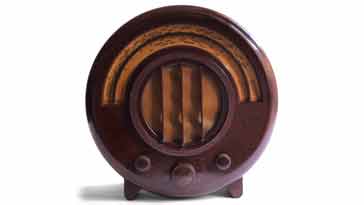
The EKCO AD65 was one of the the very popular series of Art Deco round radios that have become a classic form of radio and popular in the antique radio collectors markets.
EKCO Radios Includes:
EKCO round radio series
EKCO AD36
EKCO AD65
EKCO A22
EKCO AD75
Iconic radio receivers:
Summary of iconic radio receivers
Radio receiver history
Crystal radio sets
Development of the superhet radio
Radio history / timeline
The EKCO company, named after E K Cole, its founder produced a series of classic radios of which the AD65 was one of the most widely manufactured.
The AD65 radio was a superheterodyne design, because by this time the number of stations on the airwaves had increased to the point where the simpler tuned radio frequency or TRF radios did not have the performance and convenience to meet the needs of the ever increasingly crowded broadcast bands.
The EKCO AD65 used a total of four valves in its initial form, although later changes introduced another valve. By this time the cost of valves had fallen sufficiently for radio designers to be able to use more in a radio without making the cost prohibitive.
Courtesy Alastair Hendy [© A G Hendy]
Today all the Art Deco EKCO round radios fetch a significant premium when they reach the collectors markets. The AD65 is no exception and they reach prices several times that of other radios of their time.
Not only are they stylish, but they are also relatively compact and can fit easily within a modern room and this makes them very desirable as antique radios.
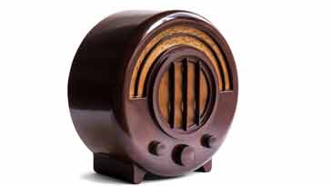
AD65 external controls & connections
The AD65 radio is very simple to use as might be expected as it was a broadcast radio for domestic use.
Although previous radio sets like crystal sets and the later TRF radios with reaction or regeneration controls that required a little skill to operate, a superhet was much easier.
On the front panel there are just three controls and these are very easy to control.
The main control in the centre s the tuning control. This is linked to the dial and there is a cord connecting the linkage to the variable capacitor and the dial indication. The variable capacitor as three gangs to control the RF tuning as well as the local oscillator.
To the right of the tuning control is the AF gain or volume control which needs little description.
To the left is the band change switch. This is a two position switch that controls all the tuned circuits that need to be changed to enable the switch between long and medium wave bands. The switch has a total of five poles that switch a variety of inductors with their taps, etc.

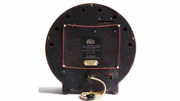
The rear of the the AD65 has the two pin mains connector. As there is no earth and the chassis is live, great care must be taken. Although all the external knobs etc act as insulators, care should be taken when any connections are made to the radio.
Another feature of the radio are the aerial and earth sockets on the back. These take the old style banana type plus. Although they appear to be isolated by capacitors from the chassis and mains via capacitors, care should still be exercised when making any connections. Check before making any connections as the old capacitors may go short circuit and connect mains to the earth or aerial.
Another feature of the rear panel is the loop antenna that can be directly connected into the antenna socket and save the need for an external antenna.
EKCO AD65 specification
The specification for the AD65 is fairly sparse in terms of real parameters measured using test equipment, but this was normal for the time.
Some of the main highlights of the radio specification are given in the table below.
| Brief Specification for the EKCO AD65 Vintage Radio |
|
|---|---|
| Parameter | Specification |
| Basic description | Superheterodyne broadcast radio of the 1930s in Bakelite Art Deco case. |
| Start of manufacture | 1934 |
| Valves (Tubes) | FC13, VP1321, PenDD4020, UR1 or CY1 - changed in later models |
| Type of radio | Superheterodyne (single conversion) |
| Intermediate frequency | 110 kc/s |
| Receiver coverage | Medium wave and long wave bands |
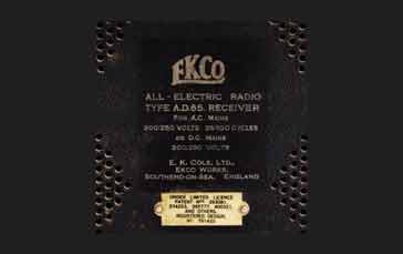
| Power | AC: 200 - 250V at 25 - 100c/s DC: 200 - 25V DC |
| Case | Bakelite: designed by Wells Coates |
| Dimensions | 15 inch diameter, 8 inches deep. |
| Colours available | Walnut, black with chrome trim, other colours available at additional cost |
| Original cost | Walnut: £11 0s 6d; Black & chrome: £11 11s 0d; Other colours: £13 2s 6d. |
Courtesy Alastair Hendy [© A G Hendy]
The EKCO AD65 was a provided quite reasonable performance for its day, and in many respects would even work well today. Its main attraction though was its styling which proved to go down well as it possessed a distinctive style which wet it out from the other manufacturers who tended to used wooden cases. In this way EKCO sets became classic radios for their era and today they are sought after and highly prized vintage radios.
EKCO AD65 valve line-up
The EKCO AD65 used a total of four valves in its initial offerings and these are listed below with their circuit functions.
| Valve Line-up for EKCO AD65 Radio Receiver Circuit |
||
|---|---|---|
| Valve Number | Type | Use within the circuit |
| V1 | Mullard FC13 | Octode with metallisation providing frequency changer (oscillator, mixer with output tuned to intermediate frequency). |
| V2 | Mazda VP1312 | Variable mu RF pentode providing IF amplification and audio preamplifier. |
| V3 | Mazda PenDD4020 | Double diode output pentode providing signal detection, AVC detection and audio output. |
| V4 | Mullard UR1 or CY1 | Double diode providing mains input rectification. |
There were some changes to the circuit that occurred later in the product life and the valve line-up changed. See the details in the section on the changes.
EKCO AD65 circuit description
The EKCO AD65 is a classic vintage radio, and the circuit is relatively straightforward as it has relatively few valves. However there are some warnings that need to be kept in mind when using or servicing the radio.
The service manual explains that the chassis is live for mains and although provision is made for the connection of a gramophone pickup or an external speaker, warning is given that "care must then be exercised to isolate them adequately." It is interesting to note this warning as no connections are provided for the external gramophone input of the loudspeaker output. It must be assumed that it was expected that people might modify the sets themselves to provide these additional capabilities.
Courtesy Alastair Hendy [© A G Hendy]
The details about the live chassis by the manufacturer in the service sheet / instruction sheet can be taken as a warning to anyone connecting them up to external peripherals as well as working on the live chassis.
There are several aspects to the operation of the circuit which consists of four valves in the initial offering.
Antenna input circuit: The aerial enters the radio via a mains isolating capacitor which is extremely important to prevent the aerial from becoming live.
The input circuit has a bandpass filter consisting of a transformer for which both windings are tuned to give adequate image rejection.
First valve: The first valve, V1 in the EKCO AD65 circuit, is a Mullard FC13 which is an octode with a metallised envelope. It acts as a frequency changer, providing the RF input, mixer and oscillator. It has an IF transformer in the anode circuit to provide the first stage of selectivity at 100 kc/s. This transformer has tuned primary and secondary windings using capacitors to bring the circuits to resonance on the required frequency Interestingly adjustable capacitors are used on each winding.
Second valve: The second valve in the AD65 line-up is a Mazda metallised VP1321. This is a variable mu RF pentode. It acts as the first IF amplifier, as well as an audio frequency triode.
For its IF function, it has a transformer in the anode circuit with tuned primary and secondary windings.
For its audio "reflex" action the valve acts as a triode with the suppressor grid voltage dropper resistor acting as the audio load resistor. The audio is then passed to V3 which is the audio double diode pentode.
Third valve: The third valve in the radio is a double diode pentode. The two diodes are used to rectify the incoming IF signal. One diode is used for the audio signal and the other for the automatic volume control, AVC which feeds back to the bias on the first valve.
The output from the anode of this valve is transformed to give the required impedance and it is then passed to the loudspeaker.
Supply input: The supply may be either AC or DC. To convert the AC waveform to DC, a Mullard half wave rectifying valve, UR1 or CY1 is used. When used with DC, the valve acts as a low value resistor, dropping little voltage.
It should be remembered that as no mains input transformer is used, the chassis is connected directly to the mains and this means it can be live and can potentially give series electric shocks.
Valve heaters: The valve heaters along with the cursor lamps are connected in series with a ballast resistor directly across the mains input. The cursor lamps connected in series, but the two are shunted by a resistor so that this block can be placed in series with the other valve heaters whilst dropping the required voltage and consuming the required current.
Courtesy Alastair Hendy [© A G Hendy]
The radio circuit, like many circuits of its day is a masterpiece of getting the maximum out of each valve, giving a number of them more than one function. In this way the number of valves was reduced, saving space and heat dissipation, but possibly more importantly cost.
Design updates
As with many designs, after the initial production some changes need to be made to improve the performance or to resolve issues that may occur with the design. This happened with the AD65 and there were some reasonably significant changes to the
There were two later versions of the AD65.
Second version of AD65: In the second version of the AD65, the valve, V2 is changed from a Mazda VP1312 to a Mullard VP13A. This has a different base and connections, but also uses a top cap for the control grid instead of the anode. As the valve bases are different, this does mean that it is not possible to substitute the incorrect valve.
Third version of AD65: In the third version of the AD65 introduced considerably more changes.
V3, the double diode and output pentode was replaced by two valves, both manufactured by Mullard. They consisted of a 2D13 double diode and a Pen26. This required a number of circuit changes to accommodate the different valve performance and circuit required.
There were also changes to the circuit around V2. Although the "reflex" action where the valve was used for both IF and AF amplification was retained, the resistor acting as the AF load which was originally in the screen grid was change to the anode circuit.
Although there were a few other minor changes to the circuit, the overall operation remained broadly the same apart from the changes mentioned.
Check out the EKCO AD65 photographed above
which is FOR SALE on: A G Hendy & Co.
The EKCO AD65 is one of the most widely seen versions of the round radio. This and the other radios in the series have a name for their Art Deco style and as such they are sought after today as desirable antique radios. The radio circuitry is relatively standard, but using valves to provide more than one function, it is exceedingly economical in its use of them - a key factor for the day as they were an expensive element of the radio.
Overall the radio design provided good performance for the day, giving the sensitivity an selectivity that was needed as the number of radio stations increased and the crystal sets that had previously been used did not provide the performance that was needed.
 Written by Ian Poole .
Experienced electronics engineer and author.
More History:
Radio history timeline
History of the radio
Ham radio history
Coherer
Crystal radio
Magnetic detector
Spark transmitter
Morse telegraph
Valve / tube history
PN junction diode invention
Transistor
Integrated circuit
Quartz crystals
Classic radios
Mobile telecoms history
Vintage mobile phones
Return to History menu . . .


