PCR Radio Communications Receiver
The PCR is a vintage radio that was introduced around 1944 and used to provide broadcast and other reception for the British forces.
Pye Vintage Radio Equipment Includes:
PCR radio
19 Set radio
Iconic radio receivers:
Summary of iconic radio receivers
Radio receiver history
Crystal radio sets
Development of the superhet radio
Radio history / timeline
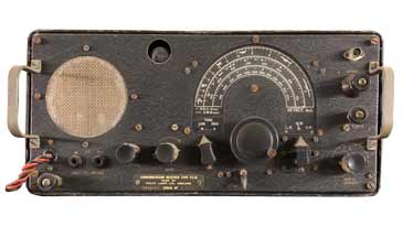
The PCR communications radio receiver, PCR stood for Portable Communications Receiver was introduced to provide the WW2 British forces with broadcast reception.
There were three variants of the PCR radio, PCR or PCR1, PCR2 and PCR3. There were minor differences between them, but essentially they were the same radio.
It is said that the PCR radio was a radio communications receiver that was intended to provide information for troops and civilians in Operation Overlord and later it was used to give for Troop entertainment.
Although it was designated a Portable Communications Receiver, the PCR is not what we would call portable today as it was contained in a 4U high 19 inch steel case, and it required an external power supply. However it was not as large and heavy as some of the other radios that were used at the time.
The radio owes much of its design and the parts used to the Wireless Sets 19 and 22 sets. Many features, parts and circuit elements were common to these sets, although, of course, there was no transmitter included within the radio and it was not intended to operate alongside one.
Basic features of the PCR radio receiver
The PCR radio was a fairly basic radio communications style set that was intended to be used for broadcast reception on the long medium and short wave bands. It was never intended for Morse operation and SSB was not used back in WW2.
It can be seen that the whole receiver has been designed to fulfil the role of receiving AM radio stations, and not uses within two way radio communications and similar applications.
| Pye PCR Communications Receiver Summary |
|
|---|---|
| Parameter | Details |
| PCR communications receiver summary | Single conversion superheteroheterodyne radio providing coverage within the MF and HF bands using six valves. An external power supply unit was required |
| Frequency coverage | Varied for the different models - see separate tables for the frequency coverage |
| Intermediate frequency | 465 Kc/s |
| Audio power output | Approx 2.5W maximum |
| Signal modes | AM - for broadcast reception |
| Introduction | April 1944 |
| Design company | Pye Ltd |
| Manufacturing companies | Pye, Philips Lamps and Invicta Radio |
| Production life | April 1944 - December 1945, although some were rebuilt between 1958 - 1960 by REME. |
Overall the PCR communications radio conformed to a standard superheterodyne radio format. Having one RF stage, then a mixer oscillator, two IF amplifiers, AM detector and then the audio amplification, the radio followed a tried and tested format. As a result, this vintage radio performed well, for a radio of its day.
The PCR radio did not have its own internal power supply. Instead it used a companion power supply. This would enable it to be used on either 250VAC or 12V DC dependent upon the power supply used.
PCR radio variants
There were three main variants of the Pye PCR radio, namely the PCR (also known as the PCR1), PCR2, and PCR3.
These variants were slightly different although the looks and many of the specifications were exactly the same.
| Pye PCR Communications Receiver Variants |
|
|---|---|
| Parameter | Details |
| PCR, PCR1 | Tuning range: 2100 - 850 Metres, 570 - 190 Metres and 5.8-18 Mc/s. Contains an internal speaker. |
| PCR2 | Tuning range: 2100 - 850 Metres, 570 - 190 Metres and 6.0 - 22 Mc/s Does not contain an internal speaker. |
| PCR3 | Tuning range: 570 - 190 Metres, 2.3 - 7.3MHz, and 7.0 - 23 Mc/s. Does not contain an internal speaker. |
Note: the frequency coverage was given in metres for the long and medium wave bands, where this was the standard way of defining the position of a station on the dial, and then in kc/s or Mc/s for the short wave bands.
As this vintage radio was used for broadcast reception, many operators would have been familiar with the wavelengths rather than frequencies for stations at home on the long and medium wave bands. Accordingly the same notation was used on this vintage radio.
PCR receiver design
The PCR radio receiver was designed by Pye Ltd in Cambridge, England and the drawings finalised in March 1944.
The PCR radio receiver was a 6 valve single conversion superheterodyne radio. Its design was based around the receiver section of the widely used WS 19 set that was used for mobile communications in the battle field.
The main differences, apart from there being no transmitter sections were that there was some additional RF input selectivity, a slightly narrower IF for better selectivity and a higher power audio output stage. This was either a 6V6 or EL32 valve dependent upon the actual model.
| Valve Line-up for R107 Vintage Radio Receiver |
||
|---|---|---|
| Valve Number | Type | Use within the circuit |
| V1 | EF39 | RF amplifier |
| V6 | ECH35 | Local oscillator and mixer |
| V2 | EF39 | 1st IF amplifier |
| V3 | EF39 | 2nd IF amplifier |
| V5 | EBC33 | Diode signal and AGC detector |
| V4 | EL32 or 6V6 | Output device |
The radio used octal valves throughout and this enabled these to be easily replaced as they were commonly available.

In terms of the circuitry, the signal from the antenna enters the radio and passes into the RF tuning stage. This gives sufficient selectivity to reduce the image response and prevent the radio suffering from large signals that are well of-channel. There is also a trap circuit across the input to reduce signals on the IF frequency and to prevent them from entering the radio.
The signals are then presented to the grid of V1 which is an EF39 pentode to provide the RF amplification.
The signals are then presented to the control grid of the V6, and ECH33 which acts as the mixer and the triode section is the local oscillator.
The anode of this stage has an RF transformer tuned to the IF of 465 kc/s and this provides tuning and coupling to the next stage. The IF has two almost identical stages - each based around an EF39 with tuned transformer coupling on the input and output.
As there are IF transformers in the anode circuits of the mixer and the two IF stages, this gives a total of three IF transformers. These are tuned and provide the selectivity for the receiver.
The signal passes to V5, a double diode triode where the AM detection was performed - a simple envelope detector was used as was normal for this era.
Not only was the audio retrieved, but the AVC voltage was also generated and applied to the grid of the RF amplifier and 1st IF stages. This reduced the gain of the radio when strong signals were being received. This prevented overload and also kept the audio output approximately level when signal strength levels varied. This was a particular benefit when receiving stations on the short wave bands where fading due to to the ionospheric propagation used would cause major changes in signal strength.
Once the audio had been recovered from the signal in the diode detector, it was then amplifier. The first stage of the amplification was in the triode section of V5, the EBC33, and the output of this stage was passed to the output pentode, V4, which was an EL34 or 6V6. The two valves were slightly different, the EL34 was an output pentode, whereas the 6V6 was a beam tetrode. Accordingly minor circuit changes were needed.
The audio output was passed to a loudspeaker - the PCR / PCR1 had its own internal speaker, whereas the later PCR2 and PCR3 required an external speaker. There were also sockets for headphones.
The PCR communications radio was a good radio for its time. While many short wave listeners and radio amateurs bought up these radios for long distance radio communication use on the HF bands, the lack of a beat frequency oscillator meant that the radio was often modified to include one.
As these radios came onto the surplus market in the 1960s, small transistor BFOs were often added, although a control for the pitch was often needed. With these and many other modifications, many of the surviving radios are not in their original condition.
 Written by Ian Poole .
Experienced electronics engineer and author.
More History:
Radio history timeline
History of the radio
Ham radio history
Coherer
Crystal radio
Magnetic detector
Spark transmitter
Morse telegraph
Valve / tube history
PN junction diode invention
Transistor
Integrated circuit
Quartz crystals
Classic radios
Mobile telecoms history
Vintage mobile phones
Return to History menu . . .