Pye WS 19 Set Vintage WW2 Radio
The Pye Wireless Set No 19 or WS 19 set was widely used by the British Forces in WW2 as an HF and VHF communications radio transceiver.
Pye Vintage Radio Equipment Includes:
PCR radio
19 Set radio
Iconic radio receivers:
Summary of iconic radio receivers
Radio receiver history
Crystal radio sets
Development of the superhet radio
Radio history / timeline
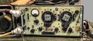
The 19 Set or Wireless Set No 19 is one of the iconic vintage radios used by the British forces in WW2 for a variety of radio communications situations.
The radio was a radio transceiver intended for radio communications use within armoured fighting vehicles, AFVs, including tanks, but its versatility meant that it was used in many more roles during the war. These additional roles and vehicle installations included jeeps, wireless trucks, ground stations and some were even installed in aircraft.
In view of the demand for these radios they were not only made by the Pye Ltd of Cambridge UK who designed them but by a number of other manufacturers both in the UK and across what was then termed the British Empire.
WS 19 set development & history
The No 19 Wireless Set is now looked upon as an iconic vintage radio that was used for military applications. However, like many other items of radio equipment, it was designed at the beginning of WW2, when it was realised that the existing radio communications equipment was not satisfactory. Even what existed was not available in sufficient quantity, and this left the forces at a severe disadvantage.
The original requirement for a radio of the type of the 19 Set had originally been issued in 1937, but with many people not wanting war again, little was done to develop the radio, and on top of this, many people did not feel that frequencies above 30 MHz were required. With both the USA and Nazi Germany using these frequencies for tactical communications, this was a requirement that needed to be added.
After the withdrawal from Dunkirk in May 1940, the British Army needed to re-equip very urgently and it needed more up to date equipment as there was a very real fear of invasion.
Radio communications was also deemed to be an essential requirement because of the fast moving nature of the "modern" warfare of the day.
In 1940, Pye Ltd of Cambridge produced a design in conjunction with the Royal Signals and Radar Establishment, RSRE, in response to the request for new tactical radio communications equipment for armoured fighting vehicles. Once designed this was rushed into production.
As such a large number of the WS 19 Sets were needed, Pye Ltd could not cope with the size of the order and therefore other British companies including AGI, Ekco, and Philips were also contracted to produce these radios.
In 1941 the supply of these radios needed to be increased still further and production was also undertaken by other countries: in Canada by Northern Electric, Canadian Marconi, and RCA Victor. Still later after the USA had entered the war, these radios were produced in the USA by Philco, RCA and Zenith.
Development did not stop with the launch of the first 19 sets, but continued so that it could be improved. As a result the Mk II version appeared in 1941 and and later the Mk III in 1942.
Along with many other vintage radio systems and receivers, the WS 19 set came onto the surplus marketplace in the 1960s. Many short wave listeners and radio amateurs picked these radios for a very reasonable sum, especially when it was considered what they must have cost to produce.
19 Set basic specification
The Wireless Set No 19 was a very rugged radio communications transceiver intended for use in the field where it would provide reliable communications up to distances of 50 miles, but also provide more local communications and an intercom facility within the particular vehicle in which it was used.
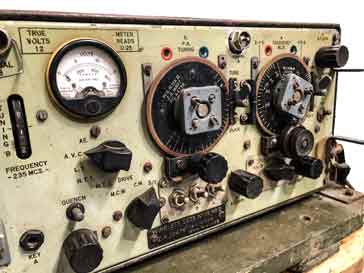
To achieve this, the WS19 radio communications unit comprised three main elements:
A Set: This was a High Frequency radio transceiver intended for radio communications at distances up to 50 miles.
B Set: This was a Very High Frequency, VHF transmitter receiver intended for short range line of sight use up to a mile.
Intercom: This was an audio amplifier that was provided to enable the operators within the armoured vehicle to communicate with each other
In addition to the basic radio itself, there were additional ancillary items including the power supply to power the unit from a 12 V DC supply and an aerial variometer used for matching the output to the whip or other form of short antenna normally used for MF / HF.
| Pye WS 19 Set Vintage Radio Communications Transceiver Summary |
|
|---|---|
| Parameter | Details |
| Specification overview | The Wireless No 19 Set was a transceiver consisting of an MF / HF high power transceiver, a short range VHF transceiver and an internal intercom. |
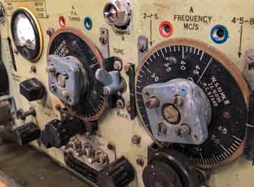
| Frequency coverage | A set: 2.5 - 6.25 Mc/s for Mk1 version 2 - 8 Mc/s for Mk 2 & Mk3 A set tuning was in two ranges B set: 229 - 241 Mc/s |
| A set receiver technology | Superheterodyne radio converting incoming signal to fixed frequency intermediate frequency for rejection of adjacent channel signals. |
| B set receiver technology | Super-regenerative detector to give selectivity and gain. |
| Modulation | A set: amplitude modulation, AM for speech, & Continuous Wave, CW and modulated continuous wave, MCW for Morse code. B set: AM speech only. |
| Intermediate frequency | 465 kc/s |
| Power output | |
| Valves | Total of 15 valves |
| Dimensions | 17.5 inches wide x 8.5 inches high x 12.5 inches deep. |
| Weight | 40 lbs. |
19 set valve line-up
The WS 19 set used a total of 15 valves (tubes) of various types within the electronic circuit design. These were spread across the A set, B set and intercom.
The summary of the valves is split into the A set receiver and sender, B set sender and receiver and the intercom.
The valves used are generally octal based valves, but obviously the 807 used for the A set sender power output is not.
The valves are numbered a "V" to indicate it is a valve, then the following numeral indicates the type numbered in sequential order of the types and then the final letter indicates the particular valve of the given type. For example V2A is the second valve type in the radio, ie.e a 6K8G and it is the first one that appears in the circuit components listing.
This type of listing was very useful when it came to maintenance as it was easier to identify the particular type of valve used, and it enabled faster identification of the valve type and hence a faster repair.
As the 19 set was a transceiver, some valves or tunes appear in the listings for more than one section as their functions often overlapped the sender and receiver, etc.
One interesting feature of this vintage radio was that the A set, had an integral mechanical feature called a flick switch that enabled the operator to change rapidly between two frequencies.
WS 19 A set receiver receiver circuit details
The receiver for the A set within the overall equipment was a fairly straightforward single conversion superheterodyne format. The signal entered the receiver and was converted down to 465 kc/s and then demodulated and applied to the audio stage.
The valve line up for the receiver is detailed below.
| Valve Line-up for 19 Set Receiver |
||
|---|---|---|
| Valve Number | Type | Use within the circuit |
| V1A | 6K7G | RF signal amplifier |
| V2A | Local oscillator & frequency changer (mixer) | |
| V1B | 6K7G | 2nd IF amplifier |
| V1c | 6K7G | 1st IF amplifier |
| V3A | 6B8G | Detector, AVC and audio amplifier |
| V2B | 6K8G | Heterodyne oscillator for BFO |
When receiving the signal enters the it is tuned by the RF tuning and then applied to the control grid of V1A, a 6K7G variable mu pentode.
The tuned output from this stage is then passed to the mixer or frequency changer that uses part of V2A, a 6K7. The local oscillator signal also enters the mixer.
The anode of the mixer stage has a coupling tuned IF transformer that is tuned to the 465kc/s frequency.
The local oscillator signal is generated by the triode section of V2A and the tuning capacitor used is ganged with those of the RF stages to ensure the correct tracking.
The tuning is in two bands, and as a result all the tuning coils for both the RF stages and the local oscillator are switched. The two bands are typically 2 Mc/s to 4½ Mc/s and then 4 ½ Mc/s to 8 Mc/s.
Once the signal has been changed down to the intermediate frequency, it passes though two stages of IF amplification based around V1B and V1C.
All the interstage coupling uses tuned IF transformers and these provide the required selectivity.
The signal from the IF is presented to a diode envelope detector contained within V3A. This also generated the voltage for the AVC which is applied to earlier stages to ensure that the gain is varied to ensure a more constant output.
The BFO is switched on for the reception of CW, but it remains off for AM and MCW.
Audio amplification is provided by the amplification section of V3A.
WS 19 A set sender
The sender or transmitter in the A set uses several elements that are common to the receiver. This actually helps the transceive capability making sure that the transmission and reception are on the same frequency.
| Valve Line-up for 19 Set Sender |
||
|---|---|---|
| Valve Number | Type | Use within the circuit |
| V2A | 6K8G | Receiver oscillator |
| V2B | 6K8G | Heterodyne oscillator & mixer |
| V5A | ARP35 or EF50 | Signal buffer amplifier |
| V4A | 807 | Transmitter RF power amplifier |
| V3A | 6B8G | Modulator on R/T, & AF oscillator & modulator on MCW |
| V6A | ARDD5 or 6H6 | Grid bias &. automatic drive control. |
the sender or transmitter shares many circuits and valves with the receiver to reduce the circuitry and also to ensure that the transmit and receive frequencies are the same.
To achieve this, the outputs from the receiver oscillator and heterodyne oscillator are mixed within valve V2B for CW to reconstitute the exact frequency for transmission.
The tuned buffer stage based around V5A, the ARP35 or EF50 ensures the correct mix output for the signal is selected and this is applied to the grid of the power amplifier stage based around V4A, an 807.
Bias for the PA is obtained from V6A and keeps the PA stage operating within its required range.
the output from the power amplifier has a low output impedance and this enables it to be coupled to the aerial variometer using a low impedance coaxial line. The variometer which is located at the base of the whip aerial is then used to match the aerial to the feeder.
WS 19 B set receiver
| Valve Line-up for the B Set Receiver |
||
|---|---|---|
| Valve Number | Type | Use within the circuit |
| V7A | E1148 or CV6 | RF amplifier |
| V1D | 6K7G | Quench frequency oscillator (super-regenerative detector) |
| V1E | 6K7G | Audio amplifier |
| V8A | 6V6 | Audio output |
The B set receiver is based around a super-regenerative detector. This type of detector is not widely used these days, but for the VHF channels used, this was an ideal way of producing a very high gain radio with a minimum of circuitry.
There are four valves in the receiver, namely an RF amplifier which also served to isolate the super-regenerative detector oscillations from reaching the antenna and being radiated. It naturally also provided RF gain.
The detector stage has already been mentioned and uses a super-regenerative approach to provide high gain and signal demodulation.
Two stages of audio amplification were also provided.
WS 19 B set sender
The B set sender or transmitter was relatively straightforward and used only three valves.
| Valve Line-up for the B Set Sender |
||
|---|---|---|
| Valve Number | Type | Use within the circuit |
| V1E | 6K7G | Audio amplifier |
| V8E | 6K7G | Audio amplifier and modulator |
| V7A | E1148 or CV6 | Master oscillator and output |
The B set sender was a relatively straightforward affair and used a free running oscillator with an audio preamplifier and then a final audio amplifier and modulator stage.
As the B set was only used for short range transmission, it provided to be perfectly adequate for the purpose for which it was designed, although it might have appeared rather crude by today's standards.
Intercommunications system, Intercom
The intercom was used for internal communications between the crew of the vehicle and it was very useful.
| Valve Line-up for the B Set Sender |
||
|---|---|---|
| Valve Number | Type | Use within the circuit |
| V1F | 6K7G | Audio preamplifier |
| V8B | 6V6G | Audio output. |
Essentially the intercom consisted of an audio amplifier which was heard by all but could be accessed for talking by all individuals. It was an essential element of the crew being able to communicate with each other as the vehicles were very noising, and direct communication would not have been possible.
The WS 19 set was a hugely successful piece of kit which provided good reliable service to the British armed forces within WW2. The 19 set is now a true vintage radio, and despite its looks and rugged appearance, it can be described as a truly iconic radio of its time.
 Written by Ian Poole .
Experienced electronics engineer and author.
More History:
Radio history timeline
History of the radio
Ham radio history
Coherer
Crystal radio
Magnetic detector
Spark transmitter
Morse telegraph
Valve / tube history
PN junction diode invention
Transistor
Integrated circuit
Quartz crystals
Classic radios
Mobile telecoms history
Vintage mobile phones
Return to History menu . . .