
Radio Signal to Noise S/N Ratio, SNR
The signal to noise ratio, SNR, S/N, is used to define the sensitivity performance of radio communications equipment particularly at HF. It uses a simple formula to calculate the SNR.
Home » Radio & RF technology » this page
Radio Receiver Sensitivity Includes:
Receiver sensitivity basics
Signal to noise ratio
SINAD
Noise Figure, NF
Noise floor
Reciprocal mixing
The signal to noise ratio, SNR or S/N ratio is one of the most straightforward methods of measuring radio receiver sensitivity.
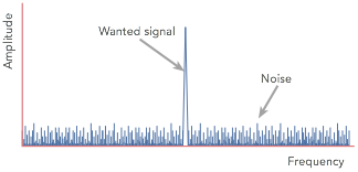
Signal to noise ratio defines the difference in level between the signal and the noise for a given signal level. The lower the noise generated by the receiver, the better the signal to noise ratio.
As with any sensitivity measurement, the performance of the overall radio receiver is determined by the performance of the front end RF amplifier stage. Any noise introduced by the first RF amplifier will be added to the signal and amplified by subsequent amplifiers in the receiver.
Video: Understanding Radio Receiver Signal to Noise Ratio, SNR
As the noise introduced by the first RF amplifier will be amplified the most, this RF amplifier becomes the most critical in terms of overall RF circuit design for the radio receiver sensitivity performance.
Accordingly, the focus of the RF circuit design for any radio receiver should focus on the initial stages of the radio as these have by far the greatest effect on the signal to noise performance.
Concept of signal to noise S/N ratio SNR
Although there are many ways of measuring the sensitivity performance of a radio receiver, the S/N ratio or SNR is one of the most straightforward and it is used in a variety of applications.
The concept of signal to noise ratio is also used in many other areas including audio systems, and many other areas of circuit design.
The signal to noise ratio of a signal in a system is easy to comprehend, and therefore it has been widely used in many areas.
However it has a number of limitations, and although it is widely used, other methods including noise figure are often used as well. Nevertheless the S/N ratio or SNR is an important specification, and is widely used as a measure of the performance of many RF circuit designs, particularly for radio receiver sensitivity
The difference is normally shown as a ratio between the signal and the noise, S/N, and it is normally expressed in decibels. As the signal input level obviously has an effect on this ratio, the input signal level must be given. This is usually expressed in microvolts. Typically a certain input level required to give a 10 dB signal to noise ratio is specified.
Signal to noise ratio definition
It is often helpful to have a concise definition of signal to noise ratio as this can make it easier to check the overall specifications in radio receiver data sheets.
Radio receiver signal to noise ratio definition:
The signal to noise ratio for a radio receiver is the difference between the wanted signal and the background noise for a given input signal level, in a given bandwidth and for a specific modulation type - if amplitude modulation is used then the modulation depth must be specified.
This signal to noise ratio definition explains the different elements of the signal to noise ratio that need to be checked when looking at any SNR specification in a data sheet, etc.
Signal to noise ratio formula
The signal to noise ratio is the ratio between the wanted signal and the unwanted background noise. It can be expressed in its most basic form using the S/N ratio formula below:
It is more usual to see a signal to noise ratio expressed in a logarithmic basis using decibels with the formula below:
If all levels are expressed in decibels, then the formula can be simplified to the equation below:
The power levels may be expressed in levels such as dBm (decibels relative to a milliwatt, or to some other standard by which the levels can be compared.
Effect of bandwidth on SNR
A number of other factors apart from the basic performance of the set can affect the signal to noise ratio, SNR specification. The first is the actual bandwidth of the receiver. As the noise spreads out over all frequencies it is found that the wider the bandwidth of the receiver, the greater the level of the noise. Accordingly the receiver bandwidth needs to be stated.
More specifically, noise power can be calculated:
Where:
k = Boltzmann's constant
T = temperature in degrees absolute
R = resistance of the circuit
It is worth noting that the noise level is independent of system impedance as the noise power is only proportional to Boltzmann's constant, bandwidth and temperature.
For radio receiver specifications, the chief aspect is the bandwidth of the measurement.
It is actually for this reason that when receiving weak signals in a radio communications system, the bandwidth is reduced to the minimum level consistent with receiving the signal with its sidebands. This reduces the thermal noise as well as off-channel interference.
Measuring signal to noise ratio
The way in which the signal to noise ratio is measured is relatively straightforward - little test equipment is needed and the method is quite easy.
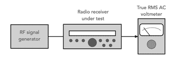
The equipment required to undertake the testing consists of two test instruments. The main one is an RF signal generator. This test instrument needs to obviously have a frequency range which covers that of the radio. It must also be possible to accurately adjust the output level down to around and below that of the anticipated level of the sensitivity of the radio under test without any signal leaking around the final attenuator in the generator. The RF signal generator must also have an output impedance suitable for the radio - typically 50Ω
The other test instrument that is required is a true RMS voltmeter that can measure the audio output from the radio.
With the generator signal switched off a 50Ω match is given to the receiver and the audio meter will detect the noise generated by the receiver itself. This level is noted and the signal turned on. Its level is adjusted until the audio level meter reads a level which is 10 dB higher than just the noise on its own. The level of the generator is that required to give the 10 dB signal to noise ratio.
The last statement was not strictly true. Whilst the first reading of the noise is quite accurate, the second reading of the signal also includes some noise as well. In view of this many manufacturers will specify a slightly different ratio: namely signal plus noise to noise (S+N/N). In practice the difference is not particularly large, but the S+N/N ratio is more correct.
The signal also has to be at a low level, and if possible the automatic gain control must be disabled otherwise the results can be skewed.
Points to note when measuring signal to noise ratio
SNR, signal to noise ratio is a very convenient method of quantifying the sensitivity of a receiver, but there are some points to note when interpreting and measuring signal to noise ratio.
To investigate these it is necessary to look at the way the measurements of signal to noise ratio, SNR are made. A calibrated RF signal generator is used as a signal source for the receiver. It must have an accurate method of setting the output level down to very low signal levels. Then at the output of the receiver a true RMS AC voltmeter is used to measure the output level.
S/N and (S+N)/N When measuring signal to noise ratio there are two basic elements to the measurement. One is the noise level and the other is the signal. As a result of the way measurements are made, often the signal measurement also includes noise as well, i.e. it is a signal plus noise measurement.
This is not normally too much of a problem because the signal level is assumed to be much larger than the noise. In view of this some receiver manufacturers will specify a slightly different ratio: namely signal plus noise to noise (S+N/N). In practice the difference is not large, but the S+N/N ratio is more correct.
PD and EMF Occasionally the signal generator level in the specification will mention that it is either PD or EMF. This is actually very important because there is a factor of 2:1 between the two levels. For example 1 microvolt EMF. and 0.5 microvolt PD are the same.
The EMF (electro-motive force) is the open circuit voltage, whereas the PD (potential difference) is measured when the generator is loaded. As a result of the way in which the generator level circuitry works it assumes that a correct (50 Ohm) load has been applied. If the load is not this value then there will be an error. Despite this most equipment will assume values in PD unless otherwise stated, but it is always worth checking if possible.
Signal to noise ratio specifications
The signal to noise ratio is often one of the parameters detailed in the specification or data sheet for a radio receiver.
In order for the specification to be meaningful, the specification must state various elements and test conditions.
Signal to noise ratio itself : This is obviously the basic specification, and it is the difference between the wanted signal and the noise.
Signal level: The level of signal has a major impact on the signal to noise ratio, and therefore the signal level must be stated. Typically when specifying a sensitivity level in terms of SNR, the signal input level required to give a signal to noise ratio of a fixed figure, typically 10dB is stated.
Bandwidth: As the bandwidth has a direct effect on the noise level, the bandwidth must be stated within the specification. Bandwidth figures used normally relate to the modulation types being used, often 6kHz for AM, 3kHz for SSB and narrower for Morse.
Modulation: The signal to noise ratio will depend upon the type of modulation used. Typically signal to noise ratio is used for AM and SSB.
Additionally it is found that when using AM the level of modulation has an effect. The greater the level of modulation, the higher the audio output from the receiver. When measuring the noise performance the audio output from the receiver is measured and accordingly the modulation level of the AM has an effect. Usually a modulation level of 30% is chosen for this measurement.
Temperature : In theory the temperature has an effect on the noise level as most of the receiver noise is thermal. Hence temperature does have an effect, but in reality, the temperature is assumed to be room temperature, 20°C.
PD / EMF: Specifications should state whether the input signal level is PD or EMF. In practice, this is rarely done and it is normally assumed the measurement is the potential difference.
Frequency: In most signal to noise ratio sensitivity specifications used in the data sheets for radio receivers, the signal to noise ratio is given for various frequency bands. As the sensitivity of the radio itself will vary for different frequencies and bands, it is necessary to give the sensitivity figures fat suitable points.
It is fairly standard for the S/N ratio specification for different receivers to be compared, generally the performance is stated for set parameters. Typically the input voltage for a signal to noise ratio of 10dB is stated.
For an HF radio communications receiver, typically one might expect to see a figure in the region of 0.5 microvolts for a 10 dB S/N in a 3 kHz bandwidth for SSB or Morse. For AM a figure of 1.5 microvolts for a 10 dB S/N in a 6 kHz bandwidth at 30% modulation might be seen.
As the sensitivity will vary according to the modulation type used, bandwidth and the frequency bands covered by the radio, often a table of figures is given to cover all the required combinations.
While there are many parameters that are used for specifying the sensitivity performance of radio receivers, the signal to noise ratio is one of the most basic and easy to comprehend. It is therefore widely used for many radio receivers used in applications ranging from broadcast reception to fixed or mobile radio communications.
 Written by Ian Poole .
Experienced electronics engineer and author.
More Essential Radio Topics:
Radio Signals
Modulation types & techniques
Amplitude modulation
Frequency modulation
OFDM
RF mixing
Phase locked loops
Frequency synthesizers
Passive intermodulation
RF attenuators
RF filters
RF circulator
Radio receiver types
Superhet radio
Receiver selectivity
Receiver sensitivity
Receiver strong signal handling
Receiver dynamic range
Return to Radio topics menu . . .


