Bridge Rectifier Circuit
The bridge rectifier consisting of four diodes enables full wave rectification without the need for a centre tapped transformer.
Diode Rectifier Circuits Include:
Diode rectifier circuits
Half wave rectifier
Full wave rectifier
Two diode full wave rectifier
Full wave bridge rectifier
Synchronous rectifier
The bridge rectifier is an electronic component that is widely used to provide full wave rectification and it is possibly the most widely used circuit for this application.
Using four diodes the bridge rectifier has a distinctive format with the circuit symbol based on a square with one diode on each leg.
In view of its performance and capabilities, the full wave bridge rectifier is used in many linear power supplies, switch mode power supplies and other electronic circuits where rectification is needed.
In view of their widespread usage, bridge rectifiers are available as single electronic components containing for diodes connected in a ring.
Some are in the form of through hole mounted components for printed circuit boards, others as surface mount components, and others are available as components that can be bolted to heatsinks. These last ones are generally used for higher current applications.
Obviously it is also possible to create bridge rectifiers from four diodes, although having four individual diodes may not be quite as convenient to use as the single bridge rectifier component.
Bridge rectifier circuits
There are many different electronic circuit designs that can use a bridge rectifier as the basis of the overall circuit, however the situation where it is used to rectify an incoming AC waveform from a transformer supply is one of the most widely seen.
A diagram of the basic bridge rectifier circuit has a bridge rectifier block at the centre. This consists of a bridge circuit which includes four diodes. These can be individual diodes, or it is also easy to obtain bridge rectifiers as a single electronic component.
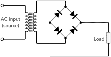
The bridge rectifier provides full wave rectification and has the advantage over the full wave rectifier using two diodes that no centre tap is required in the transformer. This means that a single winding is used for both halves of the cycle.
Wound electronic components are expensive and including a centre tap means that two identical windings, each providing the full voltage are needed to provide the full wave rectification. This doubles the number of turns and increases the cost of the transformer.
The approach using a centre taped transformer does have the benefit that only two diodes are required, one connected to the outer of each winding and the centre tap taken to earth. However the additional cost of the extra winding far outweighs the cost of the two additional semiconductor diodes required to make a bridge rectifier.
The overall cost of the power supply is normally very important when designing linear power supplies or other electronic devices.
To see how the bridge diode full wave rectifier operates it is useful to see the current flow over a compete cycle of the incoming waveform.

In most power supply applications, whether for linear voltage regulators, or for switch ode power supply applications, the output from a bridge rectifier will be connected to a smoothing capacitor as part of the load.
These electronic components accept charge during the high voltage parts of the waveform and then give out charge to the load as the voltage falls. In this way they provide a more constant voltage than the direct output from the bridge rectifier. This allows other circuits like the linear voltage regulators and switch mode power supplies to operate correctly.
Note on Power Supply Capacitor Smoothing:
Capacitors are used within many power supply applications for both linear voltage regulators and switch mode power supplies to smooth the rectified waveform which would otherwise vary between the peak waveform voltage and zero. By smoothing the waveform, it is possible to run electronic circuits from it.
Read more about Capacitor Smoothing.
In terms of the bridge rectifier and its diodes, the inclusion of the capacitor means that the current taken through the diodes will have significant peaks as the capacitor charges up.

When selecting the electronic components for the bridge rectifier, it is necessary to ensure that they can accommodate the peak current levels.
Bridge rectifiers
The bridge rectifier components can come in a variety of forms. They can be made using discrete diodes. A ring of the four diodes can easily be made either on a tag or as part of a printed circuit board. Care must be taken to ensure that the diodes are sufficiently ventilated as they can dissipate heat under load.

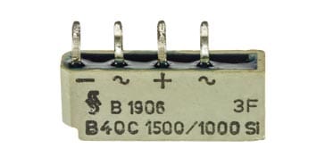
Alternatively bridge rectifiers come as single electronic components containing the four diodes in a single block or encapsulation. The four connections are brought out and marked "+", "-" and "~". The "~" connection is used to connect to the alternating input. The + and - connections are obvious.
Some of these bridge rectifiers are intended for mounting on a printed circuit board and may have wires for through hole mounting. Others may be surface mount devices.
Some bridge rectifiers are contained in larger encapsulations and are intended for mounting on a heat sink. As these rectifiers are designed to carry significant levels of current, they can dissipate significant levels of heat as a result of the diode drop and also the internal resistance of the bulk silicon used for the diodes.
Bridge rectifier circuit design considerations
Bridge rectifier circuits are relatively straightforward - there is not really much to cause an issue in any electronic circuit designs.
Nevertheless, there are several points that need to be remembered when using a bridge rectifier to provide a DC output from an AC input:
- Voltage drops: It must not be forgotten that the current flowing in a bridge rectifier will pass through two diodes. As a result the output voltage will have been dropped by this amount. As most bridge rectifiers use silicon diodes, this drop will be a minimum of 1.2 volts and will increase as the current increases. Accordingly the maximum voltage output that can be achieved is a minimum of 1.2 volts down on the peak voltage of the AC input.
Calculate heat dissipated in the rectifier: The diodes will drop the voltage by a minimum of 1.2 volts (assuming a standard silicon diode) which will rise as the current increases. It results from the standard voltage drop across the diode and also the resistance within the diode. Note that the current passes through two diodes within the bridge for any half cycle. First one set of two diodes and then the other.
It is worth consulting the data sheet for the diodes of the bridge rectifier, or the overall bridge rectifier electronic component, to see the voltage drop for the envisaged current level.
The voltage drop and the current passing through the rectifier will give rise to heat which will need to be dissipated. In some instances this can be easily dissipated by air cooling, but in other instances, the bridge rectifier may need to be bolted to a heat sink. Many bridge rectifiers are constructed to be bolted onto a heat sink for this purpose.
Peak inverse voltage: It is very important to ensure that the peak inverse voltage of the bridge rectifier, or individual diodes is not exceeded otherwise the diodes could break down.
The PIV rating of the diodes in a bridge rectifier is less than that required for the two diode configuration used with a centre tapped transformer. If the diode drop is neglected, the bridge rectifier requires diodes with half the PIV rating of those in a centre-tapped rectifier for the same output voltage. This can be another advantage of using this configuration.
The peak inverse voltages across the diodes are equal to the peak secondary voltage Vsec because over one half cycle the diodes D1 and D4 are conducting and the diodes D2 and D3 are reverse biassed.

Full wave bridge rectifier showing peak inverse voltage Assuming perfect diodes that have no voltage drop across them - a good assumption for this explanation. Using this, it can be seen that points A and B will have the same potential, as will points C and D. This means that the peak voltage from the transformer will appear across the load. The same voltage also appears across each non-conducting diode.
Bridge rectifiers are an ideal way of providing a rectified output from an alternating input. The bridge rectifier provides a full wave rectified output which enables better performance to be achieved in many instances.
Split supply bridge rectifier circuit
For many circuits like operational amplifiers, split supplies may be needed from a linear power supply. It is possible to create a split supply for these and other applications very easily using a full wave bridge rectifier. Although it returns to the use of a split transformer, i.e. with a centre tap, it can be worth it to gain a switch mode or linear power supply with the combination of both negative and positive supplies using the bridge rectifier.

The circuit operates effectively and efficiently because both halves of the input waveform are used in each section of the transformer secondary winding.
The dual supply bridge rectifier solution does require the use of a centre tapped transformer, but a second winding would often be required anyway to provide the dual supply.
The full wave rectifier circuit based around the bridge of diodes performs well and is used in most full wave rectifier applications. It uses both halves of the waveform in the transformer winding and as a result reduces heat losses for a given level of output current when compared to other solutions. Also this solution does not require a centre tapped transformer (except for the dual supply version) and as a result the costs are reduced.
The bridge rectifier is probably most known for its use in switch mode power supplies and linear power supplies, but it is also used in many other circuits as well.
 Written by Ian Poole .
Experienced electronics engineer and author.
More Circuits & Circuit Design:
Op Amp basics
Op Amp circuits
Power supply circuits
Transistor design
Transistor Darlington
Transistor circuits
FET circuits
Circuit symbols
Return to Circuit Design menu . . .