
Electronic Component Circuit Symbols
Electronic circuits are key to designing and defining electronic circuits: each different type of component has its own circuit symbol enabling circuits to be drawn and read concisely.
Ciircuits, Diagrams & Symbols Includes:
Circuit symbols overview
Resistors
Capacitors
Inductors, coils, chokes & transformers
Diodes
Bipolar transistors
Field effect transistors
Wires, switches & connectors
Analogue & functional circuit blocks
Logic
Distinct symbols have been used to depict the different types of electronic components in circuits, since the very beginning of electrical and electronic science.
Today, circuit symbols and their usage has been pretty much standardised. This enables anyone to read a circuit diagram and know what it does relatively quickly.
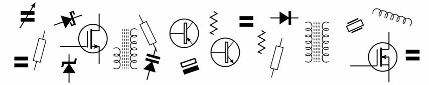
Schematic symbols are used to represent different electronic components and devices in circuit diagrams from wires to batteries and passive components to semiconductors, logic circuits and highly complicated integrated circuits.
By using a common set of circuit symbols in schematics, it is possible for electronic engineers around the globe to communicate circuit information concisely and without ambiguity. Accordingly these circuit symbols have become embedded in electronics technology and electronic circuit design.
It does not take too long to learn what the different circuit symbols mean. Often this comes along when learning about general electronics anyway. The symbols for more complicated integrated circuits and the like tend to be boxes with their type number included, and this means that there is not an infinite variety of different symbols to be learned and understood.
Although there are a number of different standards in use for the different circuit symbols around the globe, the differences are normally small, and because most systems are well known, there is normally little room for ambiguity.
Circuit symbol systems
There various different systems used for schematic symbols around the globe. Although there are some differences between them, the different standards bodies realise the need for common symbols and most are the same.
Everyone associated with electronics and electronic circuit design will be aware of the main circuit symbols such as resistors, transistors, capacitors and the like.
However it always helps to have commonality of the symbols so that even though people may not have an intimate knowlede of the various symbols, they will understand what they are from the general familiarity and usage. This would not happen if everyone used their own symbols.
Accordingly a number of standards bodies have defined their sets of circuit symbols. The main circuit symbols systems and standards bodies are:
IEC 60617: This standard is issued by the International Electrotechnical Commission, and this standard for electronic component symbols is based on the older British Standard, BS 3939 which in turn was developed from the much older British Standard 530.
Often reference is made to BS electric component standard, but the IEC standard is now the one that is used. The database includes around 1750 circuit symbols overall.
- ANSI standard Y32: This standard for electronic component symbols is the American one and is also known as IEEE Std 315. This IEEE standard for circuit symbols has various release dates.
- Australian Standard AS 1102: This is an Australian standard for electronic component symbols.
Of these the IEC and ANSI/IEEE standards for electronic symbols, i.e. schemtic symbols are those that are most widely used. Both are quite similar to each other although there are a number of differences.
However as many circuit diagrams are used globally, both systems will be well known to most electronics engineers. Many of the symbols are relatively self explanatory, although they may take a little understanding for anyone not familiar with electronics technology and electronic circuit design.
Circuit notation and reference designators
When developing a circuit diagram or schematic, it is necessary to identify the individual components. This is particularly important when using a parts list as the components on the circuit diagram can be cross related to the parts list or Bill of Materials.
It is also essential to identify components as they are often marked on the printed circuit board and in this way the circuit and the physical component can be identified for activities such as repair, etc..
In order to identify components, what is termed a circuit reference designator is used. This circuit reference designator normally consists of one or two letters followed by a number. The letters indicate the type of component, and the number, defines which particular component of that type it is. An example may be R13, or C45, etc..
By having meaningful abbreviations, it helps identifying the components much easier and it makes the circuit diagrams and board layouts more meaningful.
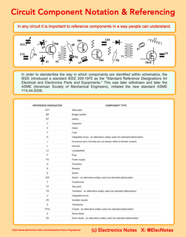
In order to standardise the way in which components are identified within schematics, the IEEE introduced a standard IEEE 200-1975 as the "Standard Reference Designations for Electrical and Electronics Parts and Equipments." This was later withdrawn and later the ASME (American Society of Mechanical Engineers), initiated the new standard ASME Y14.44-2008.
Some of the more commonly used circuit reference designators are given below:
| More commonly used Circuit Schematic Reference Designators |
|
|---|---|
| Reference Designator | Component Type |
| ATT | Attenuator |
| BR | Bridge rectifier |
| BT | battery |
| C | Capacitor |
| D | Diode |
| F | Fuse |
| IC | Integrated circuit - an alternative widely used non-standard abbreviation |
| J | Connector jack (normally but not always refers to female contact) |
| L | Inductor |
| LS | Loudspeaker |
| P | Plug |
| PS | Power supply |
| Q | Transistor |
| R | Resistor |
| S | Switch |
| SW | Switch - an alternative widely used non-standard abbreviation |
| T | Transformer |
| TP | Test point |
| TR | Transistor - an alternative widely used non-standard abbreviation |
| U | Integrated circuit |
| VR | Variable resistor |
| X | Transducer |
| XTAL | Crystal - an alternative widely used non-standard abbreviation |
| Z | Zener diode |
| ZD | Zener diode - an alternative widely used non-standard abbreviation |
Circuit diagram symbols
As there are very many different circuit symbols to cover the wide range of different components of all types, they have been split down and presented on different pages according to their categories
| Circuit Symbols Pages |
|
|---|---|
| Component type | Link |
| Resistors | Resistor circuit symbols. |
| Capacitors | Capacitor circuit symbols. |
| Inductive compoennts | Inductive component circuit symbols. |
| Diodes | Diode circuit symbols. |
| Bipolar transistor | Bipolar transistor circuit symbols. |
| Field effect transistor, FET | FET circuit symbols. |
| Wires, switches, connectors | Wires, switches and connectors circuit symbols. |
| Analogue circuit blocks | Analogue circuit blocks circuit symbols. |
| Logic functions | Logic circuit symbols. |
Circuit schematic layout guidelines
Although it is possible to simply draw a diagram or schematic for an electronic circuit design in any fashion, one of the key requirements is that it should be easy to follow.
Taking a little while to think this through before starting on drawing it can help anyone using the schematic diagram as it will be asier to follow.
Often the concepts and ideas for circuit schematics will be second nature to many people involved in electronic circuit design, but a few pointers can be helpful.
Signal flow from left to right: In general the signal flow within a circuit schematic should be from left to right. With many modern complex digital circuits, this may not always be possible, bit it can help to do this where it is appropriate.
Earth or ground lines towards bottom: It can signficantly help the layout if the earth, ground or 0V line is towards the bottom of any section. There may be one or more lines on any diagram, but it helps if the 0V line is at the bottom of any circuit section on the schematic.
Voltage rail lines to top of section: In just the same way that the zero volt line is at the bottom, the power rail is normally placed at the top. It is almsot second nature to place higher voltages higher up the diagram.
Microprocessors: With many microprocessor circuits it is not possible to have the signal flow from left to right. Often the main component of such an electronic circuit design such as the processor itself may be placed in the centre of the diagram with the peripherals placed around the periphery.
Tidiness: Whatever approach is adopted, it is wise to try to keep the diagram as tidy as possible without wires passing backwards and forwards everywhere.
Circuit symbol notations infographic
I've produced a summary infographic showing the main schematic symbol notations. This can be a useful reference when marking out a schematic, creating a bill of materials (BOM), etc.
It always helps with the understanding of an electronic circuit design, if the schematic is set out in an orderly fashion. It will be possible to any others working on the circuit to understand what is going on and where any problems may be.
Click on image for larger version
By using the various standard circuit symbols in schematic diagrams, it is possible to create a diagram that is not only easy to read, but also open to less mis-interpretation than if non-standard symbols are used.
 Written by Ian Poole .
Experienced electronics engineer and author.
More Circuits & Circuit Design:
Op Amp basics
Op Amp circuits
Power supply circuits
Transistor design
Transistor Darlington
Transistor circuits
FET circuits
Circuit symbols
Return to Circuit Design menu . . .


