Radio Antenna Directivity, Gain & Polar Diagrams
Gain & directivity are two key factors for antennas which are linked together and often plotted on a polar or radiation diagram.
Home » Antennas & Propagation » this page
Antenna Basics Includes:
Basic antenna theory
Polarisation
Resonance & bandwidth
Gain & directivity
Feed impedance
Antenna matching techniques
Antenna near & far fields
E-field & H-field antennas
Radio antennas or aerials do not radiate equally in all directions – any real radio antenna design will radiate more in some directions than others.
The actual pattern of the radiation from the antenna is dependent upon the type of antenna design, its size, the environment and many other factors and it is often plotted on a polar diagram or radiation diagram.
This directional pattern or radiation pattern, can be used to ensure that the power radiated is focussed in the desired directions, or for a receiver, the maximum sensitivity is in the desired direction.
Whatever the applications: radio communications, broadcasting, radar, mobile communications, etc, the radiation pattern with its polar diagram are important to ensure the whole system performs as required.
Polar diagrams
It is normal to refer to the directional patterns and gain in terms of the transmitted signal. It is often easier to visualise the radio antenna is terms of its radiated power, however the antenna performs in an exactly equivalent manner for reception. The figures of gain, the polar diagrams and all aspects of the performance are identical for both transmitting and receiving.
In order to visualise the way in which a radio antenna radiates a diagram known as a polar diagram is used. This is normally a two dimensional plot around an antenna showing the intensity of the radiation at each point for a particular plane.
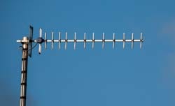
Although the radiation pattern of the antenna varies in three dimensions, it is normal to make a plot in a particular plane, normally either horizontal or vertical as these are the two that are most used. This simplifies both the measurements and also the presentation of the results. An example for a simple Yagi antenna polar diagram is shown below.

Normally the scale on the polar diagram is logarithmic so that the differences can be conveniently seen on the plot.
Antenna directivity basics
Radio antenna designs are often categorised by the type of polar diagram they exhibit. For example an omni-directional antenna design is one which radiates equally (or approximately equally) in all directions in the plane of interest.
An antenna design that radiates equally in all directions in all planes is called an isotropic antenna. As already mentioned it is not possible to produce one of these in reality, but it is useful as a theoretical reference for some measurements.
Other RF antennas exhibit highly directional patterns and these may be utilised in a number of applications. The Yagi antenna is an example of a directive antenna and possibly it is most widely used for television reception. These antennas have a main beam in one direction and a number of lobes in other directions. Accordingly these antennas are often referred to as 'beam' antennas.
One of the main objectives of the design of these antennas is to ensure that the maximum amount of energy is focussed within the main beam and that the side lobes are minimised.
Radio antenna beamwidth
There are a number of key features that can be seen from a polar diagram for an antenna.
One of the first things that may be seen for the polar diagrams of many antennas, and in particular a beam antenna is that there is a main beam or lobe and a number of minor lobes.
It is often useful to define the beam-width of an RF antenna. This is very useful when looking at directive or beam antennas such as a Yagi as the aim of the antenna is to focus the transmitted energy in one direction.
Knowing the width of the beam, gives an indication of the accuracy to which the antenna needs to be orientated when aligning it or rotating to wards the other station in the link.
The antenna beamwidth is taken to be angle between the two points where the power falls to half its maximum level, i.e. -3dB.
As a result this parameter os often referred to as the half power beam-width.

Radio antenna gain
A radio antenna radiates a given amount of power. This is the power dissipated in the radiation resistance of the Radio antenna. An isotropic radiator will distribute this equally in all directions. For an antenna with a directional pattern, less power will be radiated in some directions and more in others. The fact that more power is radiated in given directions implies that it can be considered to have a gain.
The gain can be defined as a ratio of the signal transmitted in the "maximum" direction to that of a standard or reference antenna. This may sometimes be called the "forward gain".
The figure that is obtained is then normally expressed in decibels (dB). In theory the standard antenna could be almost anything but two types are generally used.
The most common type is a simple dipole as it is easily available and it is the basis of many other types of antenna. In this case the gain is often expressed as dBd, i.e. gain expressed in decibels over a dipole.
However a dipole does not radiated equally in all directions in all planes and so an isotropic source is sometimes used. This is an imaginary type of antenna that radiates equally in all directions. When an isotropic radiator is used as the comparison antenna for determining the gain, the figures are specified in dBi i.e. gain in decibels over an isotropic source.
The main drawback with using an isotropic source (antenna dBi) as a reference is that it is only an imaginary type of antenna. It is not possible to realise one in practice and so that figures using it can only be theoretical.
However it is possible to relate the two gains as a dipole has a gain of 2.1 dB over an isotropic source i.e. 2.1 dBi. In other words, figures expressed as gain over an isotropic source will be 2.1 dB higher than those relative to a dipole.
When choosing an antenna and looking at the gain specifications, be sure to check whether the gain is relative to a dipole or an isotropic source, i.e. the antenna dBi figure of the antenna dBd figure. Figures specified in terms of dBi will be 2.1dB better than those quoted in dBd.
Antenna front to back ratio
Apart from the forward gain of an antenna another parameter which is important is the front to back ratio. This is expressed in decibels and as the name implies it is the ratio of the maximum signal in the forward direction to the signal in the opposite direction.

This figure is normally expressed in decibels. It is found that the design of an antenna can be adjusted to give either maximum forward gain of the optimum front to back ratio as the two do not normally coincide exactly. For most VHF and UHF operation the design is normally optimised for the optimum forward gain as this gives the maximum radiated signal in the required direction.
Where:
F = power in forward direction
B = power in back direction
Radio antenna gain / beamwidth balance
There are several parameters that need to be balanced when adjusting an antenna design. It may appear that seeking a high forward gain is the main requirement, but it s worth remembering that as the forward gain increases, so the beamwidth narrows.

Very narrow beamwidth antennas required accurate setting, and they must also be able to maintain their setting and not be blown about by the wind, etc.
An additional factor to remember is that as directional antenna designs have many interacting elements to them, the maximum forward gain may not correspond to other parameters like the maximum front to back ratio.
When developing an antenna, it is necessary to ensure that the design meets the actual operational requirements rather then just a theoretical specification.
The gain, directivity and the polar diagrams are key aspects of any radio antenna whether it is used for domestic broadcast reception, broadcast transmission, radio communications, mobile communications, radar or whatever. Understanding the specifications, polar diagrams, and balances that need to be made, helps when selecting an antenna for any given situation.
 Written by Ian Poole .
Experienced electronics engineer and author.
More Antenna & Propagation Topics:
EM waves
Radio propagation
Ionospheric propagation
Ground wave
Meteor scatter
Tropospheric propagation
Antenna basics
Cubical quad
Dipole
Discone
Ferrite rod
Log periodic antenna
Parabolic reflector antenna
Phased array antennas
Vertical antennas
Yagi
Antenna grounding
Installation guidelines
TV antennas
Coax cable
Waveguide
VSWR
Antenna baluns
MIMO
Return to Antennas & Propagation menu . . .