Antenna Impedance Matching Techniques
It is very important that an antenna impedance is properly matched to its feeder and there are several techniques that can be used: impedance transformers - baluns & ununs, antenna tuners, matching stubs, etc . .
Antenna Basics Includes:
Basic antenna theory
Polarisation
Antenna near & far fields
Resonance & bandwidth
Gain & directivity
Feed impedance
Antenna matching techniques
Impedance matching techniques:
Antenna delta match
Antenna gamma match
λ/4 transmission line matching
When designing or installing an antenna system it is very important to ensure that the impedance of the signal source or feeder is matched to that of the antenna system.
Ensuring that an accurate impedance match is obtained ensures the optimum power transfer and hence the optimum efficiency is obtained. This can be important when radio communications systems or broadcast transmitters are used as the performance of the antenna is crucial in these situations.
While some antenna systems utilise a high level of SWR in a twin or open wire feeder, there will ultimately need to be a good match for the transmitter to ensure the optimum power transfer.
Also if a transmitter sees a poor match, then it will not operate effectively and in some cases there could be a possibility of damage. Any radio communications or broadcast transmitter operating at a reasonable power level will need to see a good impedance match.
For receiving, ensuring a good match will ensure the best signal will be received, although sometimes the need for high performance antennas is not quite so important.
Need for antenna matching
One of the major reasons for requiring a good match between the antenna and the feeder is to ensure a low level of standing waves, SWR. Also referred to as VSWR - voltage standing wave ratio, a low level of SWR is often required for a transmitting antenna to work satisfactorily.
Although the need for a very well matched feeder and antenna combination is not as necessary for reception, for transmitting it can be crucial.
Power sent from the transmitter via a feeder will reach the antenna. If there is a poor match then power will be reflected back along the feeder.
The reflected power will set up standing waves along the feeder. There will be voltage and current peaks at various points along the feeder.
The standing waves can cause several problems for transmitting systems:
Voltage & current peaks could damage feeder: In some cases it is possible that the voltage and current peaks might damage the feeder if its limits are exceeded. High levels of current could cause local warming and could possibly melt the feeder. High voltage levels could break down the insulation. Both of these are unlikely to happen because the feeder would need to be run very close to its limits for these issues to occur.
Damage could occur to the transmitter power amplifier: If high levels of reflected power reach the transmitter power amplifier, these could cause the output devices to fail. Modern semiconductor devices can fail almost instantly if the maximum voltage level is exceeded. Also excess current caused by the reflected power standing waves could also cause the output devices to fail.
In view of this many amplifiers have protection circuitry built in to reduce the transmitter power level so that the output device ratings are not exceeded. The loss of signal power can result in lower signal levels at the receiver and could cause a radio communications link to fail.
Other output amplifiers have sufficient margin in the ratings to accommodate the high levels of SWR and reflected power. However this adds cost and unwanted capability into the amplifier which would not normally be needed.
Signal loss due to high SWR: The fact that power is reflected from the antenna results in a power or signal loss. This will reduce the effectiveness of the antenna system.

For a variety of reasons it is useful for the overall antenna system to operate with a low level of reflected power.
Note on Standing Wave Ratio, SWR & VSWR:
Standing waves are often associated with RF feeders, and they are generated when there is a mismatch between the feeder impedance and the load impedance. At th emismatch, power is reflected and the combined voltages and currents of the forward and reflected power form standing waves along the feeder.
Read more about Voltage Standing Wave Ratio, VSWR.
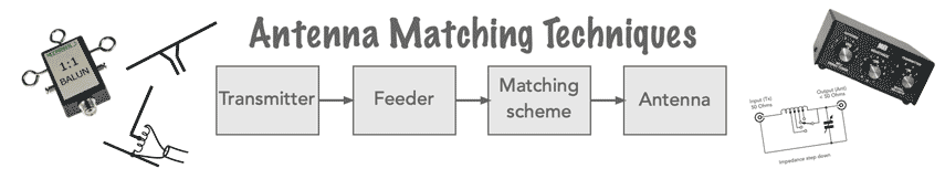
Antenna matching
In order that the antenna system presents a good match to the feeder and does not reflect power back to the transmitter, an antenna matching scheme of some form is often used.
These matching schemes can take a variety of forms from inductors acting as autotransformers in the base of the antenna, transformers such as baluns at the feed point of the antenna, to tuning or matching units that can be used to provide a variable match over a range of frequencies. Matching stubs may also be used along with a variety of other methods.

It should also be mentioned that some antennas, especially HF antennas may use a form of open wire feeder that is able to run with a high level of SWR. This form of feeder will have a very low level of loss and can tolerate high levels of SWR. However, ultimately before the transmitter, soem form of matching is needed to enable the transmitter to see the right impedance for it to operate satisfactorily.
The various methods of providing a good match will be outlined in the following sections, although some of the technique may be considered to overlap.
Antenna tuners / matching units
One widely used form of matching for an antenna is to use n inductor / capacitor based tuning or matching unit.
These antenna tuning or matching circuits can take a variety of forms. They can be built onto a printed circuit board for small transmitters in electronic equipment - everything from short range radio units, Bluetooth system and the like where small antennas of high impedance levels need to be matched to the transmitter / receiver to give the optimum operation.
They may also be used with HF transmitting and receiving antennas to provide the optimum match.
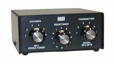
These HF antenna tuner units, ATUs are often housed in a separate box and have controls to enable them to match the transmitter and antenna over the frequency bands and ranges used.
These ATUs may be manually operated, although there is an increasing trend to be able to control them from an HF band transceiver and for the tuning to be accomplished automatically.
Note on antenna tuning unit:
Antenna tuning units can be used in a variety of ways to tune or match an antenna. This is particularly useful where transmitting stations are concerned as it enables the transmitter to be protected from high levels of standing waves and the resultant voltage and current peaks that may result in damage toth e output devices.
Read more about Antenna tuning units, ATUs.
Matching transformer in vertical antennas
Often it is necessary to provide some form of impedance transformation within the antenna itself.
Often vertical antennas need to be fed with 50Ω coaxial cable, but the impedance of a vertical is typically lower than this: often around 20&Omeag;
With this impedance and using standard coax which is 50Ω there will be a significant mismatch.
To overcome this a matching transformer is typically placed in the base of the antenna. Often this can be a straightforward coil with a tap to ensure that the correct impedance transformation is obtained.
Baluns
The matching of an antenna not only incorporates the matching of the impedance. This is very important, but another aspect of antenna matching is providing a transition from balanced to unbalanced systems.
This often occurs because many antennas, like the dipole antenna have a balanced input, whereas coax cable is often used for feeding the antenna. Coax cable is an unbalanced feeder and although it is a very convenient form feeder, a suitable transition between the unbalanced coaxial feeder and the balanced dipole antenna needs to be made.
There are many forms of balun which can be used, each one having a slightly different physical characteristic, but always achieving the balanced to unbalanced transition.
Often baluns, but not always, baluns use a 1:1 turns ratio because the impedance of the antenna and the impedance of the feeder are sufficiently matched that no additional impedance transformation is required.
Note on antenna baluns:
Baluns are used with many antennas and their feed systems to change from a balanced to an unbalanced system, or vice versa. They can take many forms and used in many antenna systems.
Read more about Antenna baluns.
Delta match
Often it is necessary to have an antenna element that is not centre fed with a break in the conductor at the centre. This is aprticaulrly useful for Yagi beam antennas where the physical construction, especially at HF means that the antenna can be made much more robust with a continuous half wave element.

This can easily be matched using what is called a delta match - it gains its name from the shape of the impedance matching arrangement.
The delta match works because it feeds the antenna at points where the voltage current rati are such that the impedance is much higher. This is very useful for antennas such as the yagi where the feed impedance is much lower than 50Ω as a result of the proximity of the parasitic elements used.
It is worth noting that the antenna delta match still requires balanced feeder to be used. This means that for any transition to unbalanced feeder such as coax will require a balun to transform the feed from balanced to unbalanced.
Gamma match
In many respects the gamma match is very similar to the delta match. Again it utilises an unbroken conductor for the driven element, but instead it connects to the centre of the antenna element, which is often connected to the boom of an antenna design such as a Yagi which can be considered as Earth potential.
It then uses an offset connection fed via a capacitor to remove the reactive elements of the feed impedance.

The gamma match or gamma feed has two main advantages. Firstly it enables the main antenna element to be constructed from a single unbroken conductor which is very useful from the viewpoint of the physical construction, especially for larger antennas where the mechanical strength is important.
However the gamma match also provides an unbalanced input, and therefore coaxial cable can be connected directly to it without the need for a balun.
The disadvantage is that there is a capacitor present that needs to be trimmed to give the optimum performance.
Quarter wavelength feeder transformers
It is possible to make an impedance matching transformer from a quarter wavelength of feeder.
By manipulating the impedance of the quarter wavelength feeder used for the transformer, it is possible to match virtually any two impedance levels, although extremes of impedance may not be quite so viable from a practical viewpoint.
The drawback of this technique is that it is not always easy to obtain the required feeder impedance for the quarter wavelength section. However if open wire feeder is used, it is possible to vary the thickness of the wires and the spacing to achieve what is required.
Coaxial feeder is a little more difficult because it is only available in a relatively limited number of impedance levels.
Nevertheless, this technique does find uses in a number of antenna designs where the matching feeder section can be incorporated into the basic antenna.
Impedance matching stubs
Matching stubs consist of lengths of transmission line, normally either coax or balanced feeder that are cut to a specific length to give the required impedance transformation.
The shorted stub can be constructed to produce a reactance of any value. This can act as impedance matching device which cancels reactive part of complex impedance.
The drawback for these stubs is that they change their value with frequency and therefore they only provide a narrowband solution. A new stub is required if any significant frequency change is made.
In addition to this, these stubs can occupy a significant length dependent upon the frequency in use.
Quarter wavelength transmission line transformers
Another technique using transmission lines or feeders to provide the match, is to use a quarter wavelength of a transmission line. Often open wire transmission line is used, but coaxial feeder is another possibility.
Using a quarter wavelength transmission line or feeder, it is possible to transform the impedance from one value to another, enabling the right match to be provided for an antenna.
Often this technique involves using a specific length of feeder which is incorporated into the antenna design itself.
Antenna matching is a fascinating subject which can bring some significant improvements in antenna performance. It is essential that many antennas are well matched to the feeder and ultimately to the source if they are to provide the best performance.
Fortunately there are many ways in which a good match can be provided and a number of very good solutions are normally available for each situation. This can be particularly useful for systems where transmitter power needs to be used very effectively: radio communications systems, radio data links, microwave links, broadcasting and the like.
 Written by Ian Poole .
Experienced electronics engineer and author.
More Antenna & Propagation Topics:
EM waves
Radio propagation
Ionospheric propagation
Ground wave
Meteor scatter
Tropospheric propagation
Antenna basics
Cubical quad
Dipole
Discone
Ferrite rod
Log periodic antenna
Parabolic reflector antenna
Phased array antennas
Vertical antennas
Yagi
Antenna grounding
Installation guidelines
TV antennas
Coax cable
Waveguide
VSWR
Antenna baluns
MIMO
Return to Antennas & Propagation menu . . .