Antenna Delta Impedance Match
The delta impedance match technique is often used with antennas where the main element needs to remain as one physical or mechanical structure
Antenna Basics Includes:
Basic antenna theory
Polarisation
Antenna near & far fields
Resonance & bandwidth
Gain & directivity
Feed impedance
Antenna matching techniques
Impedance matching techniques:
Antenna delta match
Antenna gamma match
λ/4 transmission line matching
The delta impedance matching technique is often used with antennas such as the Yagi, as well as a number of other types of antenna.
As with all antenna systems it is very important that there is a good impedance match between the antenna and the feeder. This is particularly true where transmitters are used: broadcast transmission, radio communications, HF radio systems, etc . . .
There are many ways of achieving this, but one that has gained popularity in a number of more specialist antenna scenarios is called the delta impedance match - the name arising from the actual shape of the matching configuration.
One of the main uses for the delta match is for use with large Yagi antennas. It is often useful for the main driven element to remain as one mechanically complete rod. Here the delta match can provide an ideal solution.
Delta match basics
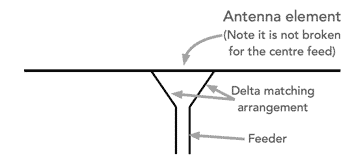
The antenna delta match system enables an antenna such as a dipole to be fed and matched while enabling a single mechanical and electrically contiguous element to be used. This can be very useful for antennas where a rigid construction is needed.
The actual feed is provided by taking the two conductors from the feeder and connecting them to points spread out from the centre as shown in the diagram.
The delta match works because it feeds the antenna at points where the voltage current ratio are such that the impedance is much higher - it typically provides a higher impedance than that of the 73Ω for a dipole in free space.
This is very useful for antennas such as the Yagi where the feed impedance is much lower than 50Ω as a result of the proximity of the parasitic elements used.
It can also be used for other antennas where a higher feed impedance is needed for any reason.
It is worth noting that the antenna delta match still requires balanced feeder to be used. This means that for any transition to unbalanced feeder such as coax will require a balun to transform the feed from balanced to unbalanced.
The impedance of the feed of an antenna such as a half wave dipole depends upon the voltage and current at a particular point on the antenna element.

Taking the example of a half wave dipole the current and voltage vary sinusoidally along its length. It is best to feed an antenna symmetrically to ensure that it remains balanced, and normally the feedpoint is taken in the centre. This provides the typically 73Ω feed impedance (in free space).
However it is also possible to separate the feeder conductors and space them further apart along the half wave element, but equi-spaced from the centre point. The radiating conductor can then remain as a contiguous conductor.

When this is undertaken it is found that the greater the spacing between the feed conductors, the higher the impedance will be.
This can be assumed from the fact that the voltage becomes higher as the distance moves from the centre point towards the end because the voltage rises and the current falls.
When determining the measurements and arrangements for a delta feed for a dipole antenna, the length for the antenna would normally be calculated in the normal fashion using the formula for a half wave dipole.
In this formula, A is the factor for the dipole and accommodates aspects such as the end effect, length to diameter ratio of the wire, etc. Typically it is often around 0,98 for HF antennas and less for VHF and UHF antennas. More information about this is available on our pages dealing with dipole antennas.
Determining the methods for the delta feed are a little more arbitrary and this work has ben based upon real life experiments as well as calculations and simulations.
Often the length A is around 0.12λ for HF antennas and about 0.115λ for VHF.
The length of the delta, denoted by the letter B is generally around0.15λ.
These estimates for the dimensions of the delta are those that are likely to work for half wave single element antennas in free space. If the element is incorporated within a a Yagi or other antenna, then further experimentation will be needed.
Unfortunately the delta is not easy to adjust, so work using antenna simulation software first is certainly recommended to give the best starting point.
The delta match system is a useful technique that can be used to good advantages on some antenna systems. Although it is not widely used, it is nevertheless a useful technique to have available for some situations. Understanding how the delta feed system works enables a good evaluation of all the possible techniques for a given antenna system whether for radio reception, two way radio communications, amateur radio, or for any one of a number of situations.
It should be remembered that when a delta match is used, balanced feeder must also be used for the feeder type. Unlike the gamma match that produces an unbalanced input where coaxial cable can be directly used, this is not the case with the delta match.
 Written by Ian Poole .
Experienced electronics engineer and author.
More Antenna & Propagation Topics:
EM waves
Radio propagation
Ionospheric propagation
Ground wave
Meteor scatter
Tropospheric propagation
Antenna basics
Cubical quad
Dipole
Discone
Ferrite rod
Log periodic antenna
Parabolic reflector antenna
Phased array antennas
Vertical antennas
Yagi
Antenna grounding
Installation guidelines
TV antennas
Coax cable
Waveguide
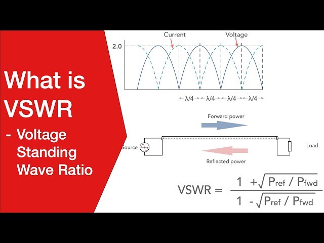
VSWR
Antenna baluns
MIMO
Return to Antennas & Propagation menu . . .