Quarter Wavelength Transmission Line Impedance Transformer
Impedance transformation or matching for antennas and feed lines can easily be accomplished using a quarter wavelength transmission line or feeder
Antenna Basics Includes:
Basic antenna theory
Polarisation
Antenna near & far fields
Resonance & bandwidth
Gain & directivity
Feed impedance
Antenna matching techniques
Impedance matching techniques:
Antenna delta match
Antenna gamma match
λ/4 transmission line matching
One elegant method of providing an impedance transformation for an antenna system is to use its transmission line to give the required impedance transformation.
This method of providing an impedance transformation for an antenna can be very elegant and can lend itself to a number of antenna designs.
The antenna will need a transmission line anyway, and if part of this can provide the impedance transformation, then it means that the feeder can be not only used to carry the power to and from the antenna, but it can also be used to provide the required impedance matching.

Quarter wave transformer matching basics
It is possible to use a quarter wavelength of transmission line to provide the required impedance matching as a result of the standing waves that are set up within the quarter wavelength transmission line and the variation in the ratio of the voltage and current will mean that the impedance see at the input and output is different.
The transformation can be expressed mathematically using the formula below:
Using this equation or formula it can be seen that and value of load impedance can be transformed to any value of input impedance using a quarter wave line of the required impedance.
The issue is in obtaining or constructing a feeder of the required impedance to give the transformation.
There are naturally limitations to the range of impedance levels that can be matched as the matching line needs to be within reasonable limits.
Typically twin or balanced feeder is used, often using wires and spacers. Using this type of feeder, it is quite easy to construct an open wire feeder of the required impedance.
The impedance of twin feeder is governed by the dimensions of the conductors, the conductor spacing and the dielectric constant of the material between them. The impedance can be calculated from the formula given below.
Where
D is the distance between the two conductors
d is the outer diameter of the conductors
ε is the dielectric constant of the material between the two conductors
As an example, when using 18 SWG wire which has a diameter of 0.125mm, i.e. radius of 0.625mm, and a spacing between the conductors of 27mm, this gives an impedance of 451Ω, i.e. virtually 450Ω
Use of coax and open wire feeder
It is perfectly possible to use virtually any form of feeder in a quarter wave matching transformer. The technique is not dependent upon the use of any particular form of feeder.
However there are a number of practical considerations to take into account in terms of the best form of feeder to use.
Normally the situation for a quarter wave feeder matching transformer will be that the two impedances or lines to be matched will have fixed levels of impedance and this determines the transformation required by the transformer.
In turn this means that as the two impedances of the lines to be matched are fixed, then the variable is the quarter wave transformer.

To gain the required transformation, the impedance of the transformer feeder needs to be varied to accommodate this. As only a limited number of coaxial feeder impedances are available, this form of feeder is not normally used, although it is possible in some cases.
Normally open wire feeder is used because it is relatively easy to make and by changing variables such as the wire thicknesses and the spacing, the impedance can be tailored to suit the needs of the transformer.
Quarter wave transformer examples
It often helps to see an example of how a particular technique is used to gain a bit more understanding of it and see the extent of the possibilities for its use. This is true for quarter wave impedance transformers.
There are many examples where quarter wave transformers are used in antenna systems to transform the impedance of one section of an antenna system to another impedance.
As mentioned before. open wire feeder is often used, but this is not always the case.
One area where this form of transformer can be used is with a half wave dipole. Here, for example the impedance can be transformed from the nominal 75Ω normally taken as the feed impedance to, say a higher value of 300Ω which could feasibly be needed in some antenna application.
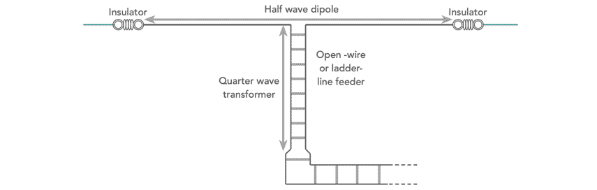
To achieve this the quarter wavelength feeder would need to be √(75 x 300) = 150Ω. The quarter wavelength open wire feeder would need to be made from 150Ω feeder.
The quarter wave transmission line or feeder impedance matching technique can be sued for a number of instances. Although the approach may require rather long lengths of feeder to be used for HF installations, often the feeder can be incorporated as part of the overall antenna. For VHF and above, the technique may still be used, bit it is not widely seen. However it can be used on printed circuit boards for microwave frequencies.
 Written by Ian Poole .
Experienced electronics engineer and author.
More Antenna & Propagation Topics:
EM waves
Radio propagation
Ionospheric propagation
Ground wave
Meteor scatter
Tropospheric propagation
Antenna basics
Cubical quad
Dipole
Discone
Ferrite rod
Log periodic antenna
Parabolic reflector antenna
Phased array antennas
Vertical antennas
Yagi
Antenna grounding
Installation guidelines
TV antennas
Coax cable
Waveguide
VSWR
Antenna baluns
MIMO
Return to Antennas & Propagation menu . . .