Random Wire Antenna
Random wire end fed antennas are very easy to erect and these antennas are ideal for many short wave listening situations.
Home » Antennas & Propagation » this page
Wire Antennas Includes:
End fed / long wire antenna
Multiple wavelength long wire
End fed half wave antenna
W3EDP antenna
Random wire antenna
Terminated long wire antenna
V beam antenna (bidirectional)
Unidirectional V beam antenna
Rhombic antenna
Beverage antenna
One of the most popular forms of antenna for people like short wave listeners is a random length of wire.
References in some books talk about installing or erecting an antenna for short wave listening that can be as long and high as possible - effectively this is a random wire antenna.
These random wire antennas can work well in some situations, but for other situations they may not be as good and they may cause various problems and issues.
Basic random wire antenna
One of the key aspects of a random wire antenna is that the length is not critical - it can be almost any length.
The fact that the antenna is a random length means that it is not cut to a length so it is optimised for a particular frequency. Instead its performance will vary over the frequency range to be used. By selecting a random length it is accepted that it will not be optimised.
This type of antenna should follow the same rules as for any end fed wire. If it is high and reasonably long, then it will pick up a good selection of signals on all frequencies.
(often referred to as a long wire antenna)
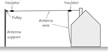
Typically a random wire antenna will have a top section and a down section as shown in the diagram, but this is not always the case - it can follow whatever shape is necessary within the space available.
However its should be remembered that any wire doubling straight back on itself will not be effective.

The diagram above shows a typical random end fed wire installation. It can be seen that the radio receiver uses an antenna tuner to match the antenna to the radio receiver input. This will help match the antenna feed impedance to that of the radio.As the current and voltage vary over the length of the antenna, using Ohm's Law, it can be imagined that the feed impedance will change. At the end of the antenna the voltage is always high and the current is zero, as there is an open circuit there.
To obtain the best performance an ATU is needed to obtain the best match between the antenna and the input of the radio.
When erecting the antenna it is good if the wire can be in the open to ensure that it is not masked by buildings or any other structure, etc that might absorb the radio signals.
It is also helpful to use insulators where the wire is fixed in any way. The high impedance points could be at positions on the antenna where the wire is fixed and it helps to use an insulator for this.
Either egg insulators, or the ribbed insulators can be obtained very easily from amateur radio dealers or from the Internet.

It is also wise to use pulleys t the mounting points so that the antenna can be taken down and put up again should this ever be required.
Care should also be taken to ensure that the antenna remains safe at all times and is not a danger to anyone nearby.
Using a random wire antenna with a transmitter
End fed random wire antennas have several drawbacks when they are used for transmitting, and as such they are not generally used in this role.
There are several drawbacks with using a random wire antenna in this way:
Antenna matching: Matching the antenna can prove to be difficult. As the antenna has a random length it will have an unknown feed impedance - it will not be selected for the frequency in use.
When using a transmitter it is very important to ensure that the transmitter sees a good impedance match. If not, the high levels of SWR that may be seen could cause the transmitter to reduce its output power to cope with the high SWR, or in some circumstances damage could occur.
High levels of radiation in the operating area: Because the random wire antenna will start to radiate energy as soon as t leaves the ATU, it can mean that strong RF fields could be present near the transmitter.
It is strongly advised these days that RF fields be kept below certain limits in any area where there may be human occupation, and with a random wire antenna, this is not the case.
Equally true, the random wire antenna will pick up signals int he vicinity of the radio room, and it could be more susceptible to interference.
Voltage and current patterns on an end fed random wire antenna
One of the key issues with using a random wire antenna is that the impedance varies considerably with the length of the antenna and the frequency that is being used.
The reasons for this is that the voltage and current vary along the length of the antenna with the voltage reaching a peak at the remote end and the current falling to zero.

The voltage and current amplitudes vary according to a sine wave back from the end of the antenna. For a quarter wavelength antenna this means that the peak current and minimum voltage occur at the feed point giving a low impedance feed which can be handled by most ATUs, etc.
However if the length is increased, then the current will start to fall and the voltage will rise indicating an increase in the feed impedance.

It can be seen that for any random wire antenna, the impedance is totally undefined. It will vary according length of the antenna in terms wavelengths at the frequency in use. Accordingly the feed impedance will vary according tot he length of the antenna and the frequency in use.
Random wire antenna and transmitters
It is possible to use end fed wire antennas with transmitters, but they tend to be set to a specific length. Also they tend to use a coaxial feeder to remove the overall antenna away from any inhabited areas. A special antenna transformer, often known as an unun (unbalance to unbalanced) is then used to provide the impedance matching required.
Another solution can be to use a coaxial feeder to ensure that the antenna is removed from any inhabited areas. A remotely controlled antenna tuning unit can then be used.
Typically for this approach, the antenna will be cut to a length where the current is high and the voltage low for the frequency being used. Typically then, a good earth will be required at the base of the antenna.
Where multi-frequency or multiband operation is required, it is sometimes possible to calculate a length where a high current point will presented at the end of the antenna for all frequencies to be used.
Normally antenna tuning units will not operate well when the current is low and the voltage is high, i.e. a high impedance feed point.
Random wire antennas may be fine for many listening applications because they are simple to install or erect and do not require any real knowledge to calculate lengths, etc. However an antenna that is cut to length for the frequencies to be used and fed or matched to give the optimum power transfer will perform better.
Antennas such as end fed half wave antennas, EFHW that use an unun to give the required match and a coaxial feeder to remove the radiating portions way from inhabited areas. Dipole antennas also work well.
 Written by Ian Poole .
Experienced electronics engineer and author.
More Antenna & Propagation Topics:
EM waves
Radio propagation
Ionospheric propagation
Ground wave
Meteor scatter
Tropospheric propagation
Antenna basics
Cubical quad
Dipole
Discone
Ferrite rod
Log periodic antenna
Parabolic reflector antenna
Phased array antennas
Vertical antennas
Yagi
Antenna grounding
Installation guidelines
TV antennas
Coax cable
Waveguide
VSWR
Antenna baluns
MIMO
Return to Antennas & Propagation menu . . .