Multi-Wavelength Long Wire Antenna
The term long wire is used for any end fed wire antenna, but a real long wire antenna is multiple wavelength long and radiates along its axis.
Home » Antennas & Propagation » this page
Wire Antennas Includes:
End fed / long wire antenna
Multiple wavelength long wire
End fed half wave antenna
W3EDP antenna
Random wire antenna
Terminated long wire antenna
V beam antenna (bidirectional)
Unidirectional V beam antenna
Rhombic antenna
Beverage antenna
Although the term long wire antenna is applied to any end fed random length wire antenna, strictly the term applies to an antenna that is long in terms of its wavelength.
In fact the definition of a long wire antenna is one that is a wavelength of more in length. In fact some long wire antennas are many wavelengths long.
With antennas of this length, the radiation directional pattern shows lobes that align more with the axis of the antenna as the length in wavelengths increases. Ultimately, the maximum radiation, and reception sensitivity aligns with the axis of the antenna.
These antennas are not widely used these days because they occupy a large amount of space and cannot be rotated easily. However they were used for some radio communication applications in the early days of radio, and in rare circumstances can be used today.
What is a long wire antenna
There are many definitions of what a long wire antenna is - in essence it is an end fed wire antenna that is long in terms of a wavelength.
In some definitions a long wire antenna is an antenna that is a wavelength or more, but other definitions imply the antenna should be several wavelengths long.
In addition to a straight wire antenna, the long wire antenna can be combined with antennas of various shapes to increase the gain over that of a single wire antenna.
Long wire antenna characteristics
If a wire antenna is half a wavelength long, then it will perform very much like a dipole, the main difference being that it is end fed.
The radiation pattern for a dipole is given in the diagram below.

The same radiation pattern is exhibited for an equivalent end fed wire, however, as the length of the end fed wire is extended in terms of the number of wavelengths, it is found that the radiation pattern becomes more complicated.
A number of different lobes form and these move out towards the the line of the axis of the wire of the antenna, aligning further with this as the length is extended.
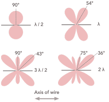
It can be seen that the radiation pattern of this long wire antenna is very different to that of the half wave antenna. As the length of the antenna increases, so the major lobes align further with the axis of the antenna.
For a very long wire antenna, it can be considered as what is known as an end fire antenna.
| Radiation Pattern of Half Wavelength Antenna | ||
|---|---|---|
| Lobe | Max radiation | -3dB |
| Main Lobe | 90° | 50° |
| Radiation Pattern of a One Wavelength Antenna |
||
| Main Lobes | 54° | 31° & 72° |
| Radiation Pattern of a Three half Wavelength Antenna |
||
| Main Lobes | 43° | 31° & 72° |
| Secondary lobe | 90° | 71° |
| Radiation Pattern of a 2 Wavelength Antenna |
||
| Main Lobes | 36° | 24° & 45° |
| Secondary lobe | 75° | 60° & 90° |
Understanding directive pattern of long wire antenna
The reason for the differing radiation or directive patterns of long wire antennas as the length increases may not be intuitively obvious at first sight. It comes from the phases of the waveform on the antenna. These add and subtract at different angles.
It is the current flowing within the antenna that gives rise to the radiation and very simply these can be considered as radiation sources for this qualitative description.
For a half wavelength antenna, the pattern is simple, but as the lengths increase there are further current maximum regions and the radiation from them will add and subtract at different angles.
As the long wire antenna length is increased, so the number of radiation sources increases and the pattern becomes more complex.
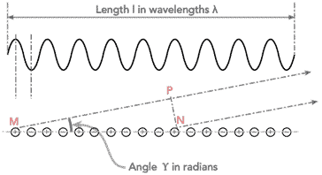
In the diagram it can be seen that the antenna is multiple wavelengths long as seen by the current pattern at the top.
For the radiation to be reinforced the sum of the different radiation sources must add, and for a minimum they must subtract.
To take the general situation shown int he diagram, the radiation is at a minimum when the wavefronts from the sources are out of phase with each other. This occurs when MN - MP = n x λ/2 where n is an odd integer.
Where:
length l is in wavelengths
γ is in radians
The signals reinforced when the wavefronts from the different sources are in phase and this occurs when MN - MP = nλ where n is an integer.
Gain & angles of long wire antennas
As the long wire antenna becomes longer in terms of its wavelength, so the main lobes fall increasingly in line with the axis of the antenna wire.
The gain of the antenna also increases as the lobes become more directive with increasing number of wavelengths.
Although there are pronounced major lobes, there are also many minor ones - these tend to be more numerous as the length of the antenna increases in terms of wavelengths.
| Gain and Angles for Major Lobes on Long Wire Antennas | ||
|---|---|---|
| Length (λ) | Angle of main lobe | Gain (dBd) |
| 1 | 54° | 0.4 |
| 1½ | 42 | 1.0 |
| 2 | 36° | 1.5 |
| 2½ | 33° | 1.8 |
| 3 | 30° | 1.8 |
| 4 | 26° | 3.3 |
| 5 | 22° | 4.2 |
| 6 | 20° | 5.0 |
| 8 | 18° | 6.4 |
| 10 | 16° | 7.4 |
Notes:
• The gain of the major lobes is measured in decibels compared to a dipole, dBd.
• The figures are given for the major lobes as shown in the diagrams above.
• Apart from the major lobe, there are also minor ones with less gain.
Use of long wire antennas
Multiple wavelength long wire antennas, distinguishing them from the random wire "long wires" are not widely used as they require significant space. These days Yagi antennas tend to be used, even at HF where they tend to be more effective and flexible as they can be rotated easily. That said a long wire could be used on lower frequencies where it would be impracticable to construct a Yagi.
Long wires tended to be used in the early days of wireless before antennas like the Yagi had been invented.
Even then the long wire tended to be grouped to form antennas like a V-beam (not to be confused with an inverted V dipole), or a rhombic, etc.
These antennas might be used where fixed directional properties are required.
The true multiple wavelength long wire antenna is not widely used these days, although in the early days of wireless it provided an effective way of producing a directional antenna, especially when it was used as part of a V-beam or rhombic antenna.
 Written by Ian Poole .
Experienced electronics engineer and author.
More Antenna & Propagation Topics:
EM waves
Radio propagation
Ionospheric propagation
Ground wave
Meteor scatter
Tropospheric propagation
Antenna basics
Cubical quad
Dipole
Discone
Ferrite rod
Log periodic antenna
Parabolic reflector antenna
Phased array antennas
Vertical antennas
Yagi
Antenna grounding
Installation guidelines
TV antennas
Coax cable
Waveguide
VSWR
Antenna baluns
MIMO
Return to Antennas & Propagation menu . . .