Multiband End Fed Half Wave EFHW Antenna
The end fed half wave, EFHW antenna provides a very attractive option for many antenna installations including those for commercial radio communication and multi-band ham radio operation
Home » Antennas & Propagation » this page
Wire Antennas Includes:
End fed / long wire antenna
Multiple wavelength long wire
End fed half wave antenna
W3EDP antenna
Random wire antenna
Terminated long wire antenna
V beam antenna (bidirectional)
Unidirectional V beam antenna
Rhombic antenna
Beverage antenna
The end fed half wave antenna is an attractive option for many radio hams as it is able to provide multiband operation without the use of traps or stubs whilst occupying a minimum amount of space and not presenting a very ugly visual impact.
A broad-band matching network is typically used to transform the high impedance of the EFHW feed point to 50Ω suitable for standard coax cable.
The end fed half wave antenna can be operated with a small counterpoise, and in some instances, no counterpoise is used at all, although this is not necessarily wise. The lower end of the antenna may also be grounded as an alternative to reduce static noise.
Being a single wire, and end fed it is very easy to set up, often taking only minutes to do and this makes it ideal for ham radio portable operation, as well as for base station usage.
The end fed half wave antenna is also ideal for many commercial radio communication applications as well.
End fed half wave antenna basics
We are all familiar with a centre fed half wave dipole antenna. In free space this presents and impedance of 72Ω to the feeder and this means that it provides a relatively good match to 50Ω coax cable, especially when the proximity pf the ground and other objects will tend to reduce the feed impedance.
When the feeder is connected to the end of a half-wave antenna, the situation is quite different. Here the feed impedance is very much higher, and to enable a good match to be made to 50Ω coax which is normally used a matching device is required, otherwise there will be a discontinuity and power will be reflected.

In view of the fact that the antenna feed point occurs at a high voltage point on the radiating element, these antennas are sometimes known as voltage fed antennas.
To provide the match at this point a transformer is normally used and this gives an impedance transformation. Typically the matching transformer transforms the impedance from the value of around 4,000 or 5,000 Ω at the EFHW antenna feed point down to the 50Ω value of the coaxial feeder.
The end fed half wave antenna is also able to provide multi-band operation. It can be used on all odd and even harmonics of the fundamental frequency, presenting the same high impedance at these frequencies.
The end fed half wave antenna is also able to provide multi-band operation. It can be used on all odd and even harmonics of the fundamental frequency, presenting the same high impedance at these frequencies.
End fed half wave antenna for amateur radio bands
One of the advantages of the end fed half wave antenna is that it operates at both odd and even multiples of a half wavelength. A voltage point is present at all odd and even half wavelengths. This does not hold true for a half wave dipole - this is fed at a current maximum and this only occurs at the centre of the dipole for odd multiples of a half wavelength.
| Example of multiband operation of an End Fed Half Wave Antenna | ||
|---|---|---|
| Harmonic of Fundamental | Frequency (MHz) | Comments |
| 1 | 3.55 | Fundamental operation at bottom end of 80 metres |
| 2 | 7.1 | Between CW and phone sections of 40 metres |
| 3 | 10.65 | Would need Antenna tuner to operate between 10.1 and 10.15 |
| 4 | 14.2 | |
| 5 | 17.75 | Would need antenna tuner to operate between 18.068 and 18.168 |
| 6 | 21.3 | Within SSB portion of 15 metres |
| 7 | 24.85 | Not far from 24.89 and 24.990 12 metre band |
| 8 | 28.4 | Within SSB section of 10 metres. |
End fed half wave antenna length
As the name indicates the EFHW antenna is half a wavelength long on the lowest band of operation.
However the physical length is slightly different to that of a half wavelength in free space. This results from a variety of factors associated with the fact that the current is flowing in a wire of finite length. One key factor is what is termed the end effect.
A variety of figures are used for determining the length of the half wave antenna. The factors used in the formulas below take into account the antenna wire end effect and the thickness of the the wire, assuming typical wire thickness is used.
Some calculation is required to select the optimum fundamental frequency that will also work with the higher frequency bands. This will depend upon which bands are of most importance, and also the section of the bands which are to be used. This is a personal choice that will depend upon preference. This is likely to be a bit of a compromise because the optimum length for for one band may not fit with another so easily. However the discrepancies can be overcome using an antenna tuner by the transceiver to reduce any high levels of SWR. If coaxial cable with a low loss at the frequency of operation is used, then the losses resulting from a higher than anticipated SWR will be low.
Once the fundamental operating centre frequency has been determined, then the length can be determined.
As mentioned before the lengths are a little variable according to the exact nature of the antenna. Cutting the length slightly longer than required and then trimming to obtain the best operation is always the right way to set up the antenna.
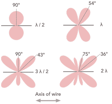
EFHW radiation pattern
One point to remember about the end fed half wave antenna is that the radiation pattern will change according to the band on which it operates and hence the number of half wavelengths it uses.
When used as a half wave radiator it will perform in the same way as a half wave dipole with the familiar figure of eight pattern, radiating to the maximum at ninety degrees to the axis of the wire.
As the length increases, the radiation pattern changes with additional lobes forming, and the maximum points of radiation moving away from being at right angels to the axis of the wire and moving towards alignment with the axis of the wire.
EFHW transformers & Ununs
In order to match the end fed half wave antenna to the coaxial feeder, it is necessary to have a matching network or transmission line transformer. The coaxial feeder is likely to be 50Ω and the antenna impedance is possibly around 4000 or 5000Ω, the impedance needs to be matched.
Often a transformer is used to perform this match. As it matches an unbalanced load to an unbalanced load, these transformers are often referred to as "ununs" as opposed to the more familiar balun that matches a balanced to unbalanced line.
The impedance transformation is approximately 50:5000 or 1:100. As the impedance at this point is not well defined, many people use a 1:9 transformer, although this only matches to an impedance of 450Ω. It is far preferable to use a 1:49 or 1:64 ratio.
There are several requirements for these transformers in terms of electrical performance. At low frequencies, like all transformers, they require adequate primary inductance at lowest freq.
Note on antenna ununs:
Ununs are used to provide an impedance transformation while keeping an unbalanced feed regime - the name unun is shortened from the words unbalanced to unbalanced. In many respects ununs are similar to baluns but where the input and output are both unbalanced.
Read more about Antenna ununs.
Variants of end fed antennas
There are various versions of end fed antennas on a very similar theme. These utilise the same basic concept but have slight variations.
- W3EDP antenna: The W3EDP antenna is a form of end fed wire that has been in use for many years and was first described in 1936.
Read more about . . . . W3EDP antenna.
End fed half wave antennas have become very popular as a very convenient low visual impact antenna that is easy to erect for home and also for portable use. It is straightforward and build, and quite low cost. There are also many options are available to purchase. With a little care, the end fed half wave, EFHW antenna is an ideal choice for many ham radio, and even other forms of radio communication station.
 Written by Ian Poole .
Experienced electronics engineer and author.
More Antenna & Propagation Topics:
EM waves
Radio propagation
Ionospheric propagation
Ground wave
Meteor scatter
Tropospheric propagation
Antenna basics
Cubical quad
Dipole
Discone
Ferrite rod
Log periodic antenna
Parabolic reflector antenna
Phased array antennas
Vertical antennas
Yagi
Antenna grounding
Installation guidelines
TV antennas
Coax cable
Waveguide
VSWR
Antenna baluns
MIMO
Return to Antennas & Propagation menu . . .