
Coaxial Collinear Antennas
One very popular form of collinear antenna is the coaxial collinear as this provides an elegant method construction, especially for experimenters, radio amateurs, etc.
Home » Antennas & Propagation » this page
Phased array antennas includes:
Phased array antenna basics
Collinear antenna
Coaxial collinear
Beamforming & beamsteering antennas
The coaxial collinear antenna is an ideal solution for many people wanting to construct a form of collinear antenna relatively easily.
Although this form of antenna is popular with radio amateurs because the construction is quite easy, it can also be used for many other forms of radio communications. It could be used within the base station of a two way radio communications system. It is particularly popular for VHF and UHF radio communications because the size is not too large and it provides a good level of gain
As the name implies the coaxial collinear antenna utilises sections of coaxial feeder to make up the antenna.
To prevent moisture ingress and deterioration from other environmental factors, the antenna is normally housed in a plastic or fibreglass hollow tube. This makes an elegant looking antenna that has a good structure and is able to withstand the weather.
How a coaxial collinear works
The coaxial collinear is a form of phased array antenna. The various antenna sections or elements are all on the same axis, making them collinear in their geometrical position, i.e. they form a coaxial collinear phased array antenna.
Although there are many different configurations that can be used, one popular format is for an antenna formed from a series of half wavelength coaxial sections or segments with the inner and outer connections transposed at the junction of each half wave section, i.e. the inner connected to the outer, and the outer connected to the inner.
The final section of the antenna has a number of options. In some instances a short circuit may be used, whereas in others a final quarter wavelength element may be used.
Although the antenna may be used in a balanced format as seen below, it can also be used as a monopole with the appropriate feed matching, etc.
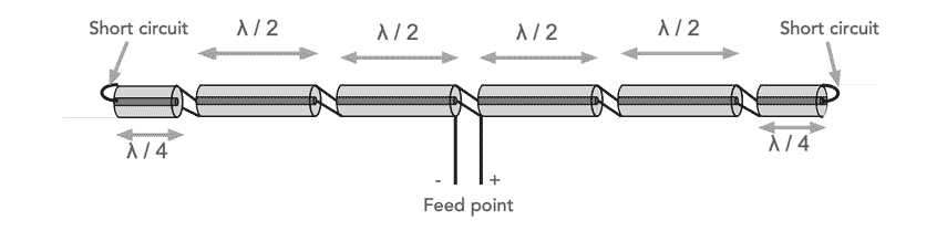
To see how this operates, first look at the outer sections. These have a short circuit a quarter wavelength along the feeder. This means that at the end of this element, the impedance seen will be transformed from a short circuit to a high impedance.
In this way the interface between the two segments sees a high impedance, all the way back to the feed point.
It will be seen that the feeder used is a high impedance open wire or balanced feeder. This can be transformed in some form of impedance matching circuit to give a good match to the more usual low impedance 50Ω cable.
In terms of the actual operation, the segment ends have a voltage of amplitude and phase close to the antenna driving voltage.
As the inner is connected to the outer of the coax at each half wavelength, this means that the currents flowing on the outer surface of the coax segments are the same for a given half of the antenna.
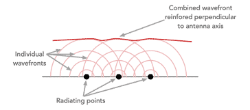
As the currents are in phase with each other, this means that each segment radiates a signal with the same phase. These constructively combined when they are at right angles tot he axis of the antenna.
To understand and look a little more closely at the operation of the antenna, it can be considered as two antennas as there are two conductors for each section of the antenna - one is the inner of the coax and the other the outer.. Effectively one antenna is inside the other, although this alternatives every half wavelength.
As would be anticipated because of the fact that feeder is being used, the current flows in the conductors of each section are equal and opposite.
By alternating the conductors every half wavelength gives the in-phase radiating sources which makes this a phased array antenna, and as a result of the fact that there is no phase shift between the sections the radiation is perpendicular to the axis of the antenna.
Monopole vertical coaxial collinear
Although the antenna described above could be used, most uses for collinear antennas (but not all) are for a vertical monopole antenna and with a base feed. A few simple modifications can bring about the collinear with which more people are familiar.
This can make it a very useful form of antenna for many two way radio communications applications from taxi, emergency service base stations to radio amateurs and their VHF UHF stations.
Obviously the first change is to orientate the antenna in a vertical fashion, but there are a few other changes to enable the antenna to operate in the fashion required. Sometimes there will be different methods of achieving the same end, but these are some that are more widely used.
The first one is to replace the quarter wave shorted stub at the extremity of the antenna with a quarter wavelength of wire. This forms the top section of the antenna and it is connected to the inner or centre conductor of the adjacent coax section. It is not connected to the outer conductor at all.
The length of this element can be determined by calculating the length of a quarter wavelength of the signal at the operating frequency in free space and then adding a small correction factor for what is termed the end effect.
Where:
L1 = length of quarter wavelength top section in metres
f = frequency in Hz
A = end effect factor and often between about .95 and .98.
Note: the factor of 300 x 106 is used in the equation because it is the speed of light in free space.
The number of half wavelength sections incorporated into the main section is dependent upon the size of the antenna permissible. Often between two and four are used, but some antenna may use many more.
The length of these elements is an electrical half wavelength for the signal travelling in the coaxial feeder. It is necessary to check the velocity factor of the coax being used, but it is often about 0.66. However it is essential to check this as it has a major impact on the length and if the length of the antenna elements are incorrect then the antenna could be hopelessly wrong.
The length of these half wave elements is calculated from the formula given below:
Where:
L2 = length of half wave sections in metres
f = frequency in Hz
V = is the velocity factor of the coax cable.
Note: when cutting the coax to length, some extra will need to be allowed for making the connections at each end.
The final section of the antenna is the bottom section. This is required to transform the high impedance seen at the end of the bottom half wave section to an impedance that gives a suitable match to 50Ω.
There are several ways of doing this, one would be to use a quarter wavelength of open wire of ribbon feeder. Other approaches that can be sued are often seen with the J-pole antenna where a feed / matching quarter wave stub is used to match to the 50Ω coaxial cable.
The quarter wavelength acts as a transformer to provide a high to low impedance transformation.
In view of the high impedance feeds, etc, it is wise to ensure this does not travel along the outer of the coaxial cable and it is wise to remove this. One effective means of achieving this is to place some suitable ferrite beads over the coax cable after it has left the tubing.
Coaxial collinear antennas are an easy method of creating an effective VHF or UHF antenna. They can be relatively easy to construct using materials that are easily available and for comparatively little cost.
The construction of a collinear antenna can be a good antenna project for many hobbyists, and for commercial installations, suitable collinear vertical antennas are widely available.
 Written by Ian Poole .
Experienced electronics engineer and author.
More Antenna & Propagation Topics:
EM waves
Radio propagation
Ionospheric propagation
Ground wave
Meteor scatter
Tropospheric propagation
Antenna basics
Cubical quad
Dipole
Discone
Ferrite rod
Log periodic antenna
Parabolic reflector antenna
Phased array antennas
Vertical antennas
Yagi
Antenna grounding
Installation guidelines
TV antennas
Coax cable
Waveguide
VSWR
Antenna baluns
MIMO
Return to Antennas & Propagation menu . . .


