50Ω vs 75Ω Coax Cable - Which is Best for What and Why
There are two main standards for the impedance of coax cable: 50Ω and 75Ω so why are there these two main standards and what are their advantages?
Home » Antennas & Propagation » this page
Feeders Tutorial Includes:
Feeder types
Coaxial cable, or "coax," is a fundamental component in virtually all modern electronic communication systems where it carries radio frequency signals from one point to another.
Yet, within the world of coax, two impedance values: namely 50Ω and 75Ω dominate the landscape.
These two standards, while structurally similar, were developed for entirely different purposes and they have slightly different characteristics that make them applicable for slightly different purposes.
Understanding the historical context, the physics underpinning these specific impedance values, and the advantages of each is key to correctly designing any high-frequency system, from the smallest wireless device to the largest cable TV network.
Why two standards?
The development of two distinct coaxial cable impedance standards was driven as a result of two different goals in electrical engineering: maximizing power transfer and minimizing signal loss (attenuation).
The optimal points for these different requirements do not coincide, leading engineers to select a compromise best suited for the intended application.
The mathematics of optimal impedance
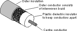
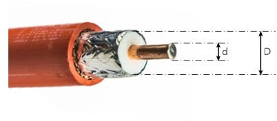
The characteristic impedance, often designated Z0 of a coaxial cable is determined by the physical geometry of the cable. The main determining factor is the ratio of the outer diameter of the inner conductor to the inner diameter of the outer shield, as well as the dielectric constant of the insulating material separating them.
The formula for characteristic impedance is:
Where:
Zo = Characteristic impedance in Ω
εr = Relative permeability of the dielectric
D = Inner diameter of the outer conductor
d = Diameter of the inner conductor
Note: The units of the inner and outer diameters can be anything provided they are the same, because the equation uses a ratio.
By mathematically analyzing the properties of the coax cables against their impedance two impedance sweet spots were deduced:
Maximum Power Handling - approx 30Ω: Analysis showed that for a standard coaxial structure, the maximum amount of power could be transmitted if the impedance was around 30Ω. However, cables in this range require a very thick inner conductor relative to the shield, leading to practical and manufacturing challenges.
Minimum Attenuation - approx 77Ω: Analysis also showed that the theoretical minimum signal loss (attenuation) occurs at an impedance of approximately 77Ω. This impedance represents the optimal physical configuration to minimize energy dissipation within the cable.
These are the most widely mentioned scenarios, but there is another one that is mentioned less frequently:
Highest voltage - approx 60Ω: This arises as a result of the electric field between the center conductor and the outer conductor in the air-filled coax cable. The electric field is maximized when the conductor is constructed such that its impedance is approximately 60Ω.
In practice, neither 30Ω nor 77Ω were adopted directly. Instead, they were adjusted to cleaner, more practical, and standardized values: of 50Ω and 75Ω.
60Ω cable is rarely used because it is not so widely necessary to maximise the voltage withstand capability.
50Ω coax cable standard
The 50Ω standard is probably the more commonly seen - both in use and also in the products stocked by electronic component distributors.
Accordingly it is worth taking a deeper looking into the various aspects of this coaxial cable.
Development of the 50Ω standard
The 50Ω standard emerged during World War II, primarily driven by the needs of high-power military radio and radar systems.
The focus was squarely on transferring the maximum possible power from transmitters to antennas.
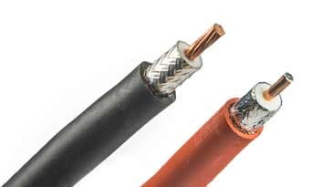
Compromise for Power and Practicality: While the theoretical maximum power point is closer to 30Ω, 50Ω was adopted as the best practical compromise. A $ 50Ω cable maintains a high power handling capacity while being much easier to manufacture and offering a significantly lower attenuation than a 30Ω cable.
Antenna Matching: Most standard dipole and monopole antennas, when placed near a ground plane (typical in radar and mobile applications), exhibit a feedpoint impedance close to 50Ω$. Using a 50Ω cable naturally provides a near-perfect match to these antennas, minimizing signal reflection (Standing Wave Ratio, or SWR).
50 Ohm Coax: advantages & disadvantages
The 50Ω standard is the most common format for coax cable for radio frequency or RF systems and applications.
It is the format used for all forms of communications equipment, RF test equipment and the like for cellular networks, microwave links, satellite communications, amateur radio, and in fact any aspect of radio communications.
Advantages of 50Ω coax
Excellent power handling: The geometry required for 50Ω (a relatively thicker inner conductor) allows the cable to safely dissipate the heat generated by high-power transmission. This is crucial for transmitters where wattage can range from tens to thousands of watts.
Optimal match to RF systems: Most active RF components (transmitters, receivers, filters, amplifiers, circulators, etc.) are internally designed to have a 50Ω input and output impedance. This standardization ensures that systems can be easily interconnected without needing bulky, lossy impedance matching networks.
Mechanical robustness: 50Ω cables, particularly large military-grade types like RG-8, are often built to be physically tougher to withstand harsh environmental conditions.
Standardised connectors: The entire ecosystem of high-frequency connectors—including N-type, SMA, BNC, and TNC—is overwhelmingly standardized for 50Ω impedance, ensuring seamless interoperability.
Disadvantages of 50Ω coax
Higher attenuation (loss): Compared to an equally constructed 75Ω cable, a 50Ω cable will exhibit slightly higher signal loss over the same distance, especially at very high frequencies.
Often higher cost: Due to the more robust construction and thicker inner conductor needed to handle high power, many 50Ω cables can be more expensive than their 75Ω counterparts.
Main applications of 50Ω coax
The 50Ω impedance standard is dominant in any application that involves transmitting power or where system standardisation is paramount.
Radio Communications: Amateur (Ham) radio, CB radio, two-way land mobile radio (LMR).
Wireless Data Networks: Wi-Fi access points, cellular base stations (towers), and all interconnecting cabling.
Military and Radar: All radar systems, jamming equipment, and military communications links.
Test and Measurement: All high-frequency laboratory equipment (oscilloscopes, spectrum analyzers, network analyzers) use 50Ω inputs/outputs to ensure accurate and repeatable measurements.
Microwave and Satellite: Feed lines for satellite dishes and microwave links.
75Ω coax cable standard
Although possibly less widely used and less commonly seen int he general electronics scene, 75Ω coax cable is still an important player.
It is found in many areas of electronics and electronic systems, having its own niche where its performance means it is the best option to use.
Development of the 75Ω standard
The 75Ω standard was developed later, largely driven by the telecommunications and broadcast industries where the goal was to transmit weak signals over long distances with the least possible loss.
Optimal for low loss: 75Ω is close to the theoretical optimum of $77 \Omega$ for minimum attenuation. By minimizing loss, signals retain their strength over long cable runs, reducing the need for expensive and complex amplifiers.
Matching receiving antennas: Receiving antennas, particularly TV and broadcast antennas (like a folded dipole), often present a feedpoint impedance close to 75Ω or $300 \Omega$. Using a 75Ω cable allows for efficient coupling to these receiving systems.
75 Ohm Coax: advantages & disadvantages
The 75Ω standard is the backbone of the consumer video and internet infrastructure. It thrives where the objective is to maximize the purity and integrity of a signal being transported over long distances.
Advantages of 75Ω coax
Lowest Attenuation (Minimum Loss): This is the single greatest advantage. 75Ω cables offer the best possible signal transmission with the least amount of energy lost to heat over long cable runs. This is critical when dealing with weak, passively received signals or signals that must travel miles without amplification.
Optimal for Video Signals: The inherent impedance of many unpowered video components, such as passive filters and splitters used in cable television distribution, naturally aligns well with the 75Ω standard.
Lower Cost (Typically): The physical geometry of 75Ω requires a thinner center conductor than 50Ω, which translates to less material cost for bulk production, making it the economical choice for mass-market applications like residential cable TV.
Disadvantages of 75Ω coax
Lower Power Handling: The thinner center conductor needed for 75Ω cannot dissipate heat as effectively as the thicker center conductor in a 50Ω cable. Attempting to run high RF power through 75Ω cable can lead to overheating, cable failure, and dielectric breakdown.
Less Standardized in RF: While it is the standard for video, it is rarely used in the active components of RF transmitters and receivers, which are almost universally 50Ω.
Main applications of 75Ω coax
The 75Ω impedance standard is dominant in applications involving video, digital broadband data (cable modem), and signal distribution.
Cable Television (CATV): From the cable company’s street cabinet to the user's TV set, the entire infrastructure uses 75Ω cable (typically RG-6 or RG-59).
Broadband Internet (Cable Modem): The DOCSIS standards used by cable providers rely on the 75Ω infrastructure for transmitting high-speed digital data.
Video Distribution: Professional video signals (HD-SDI and 3G-SDI) in television studios are carried almost exclusively by 75Ω coax.
Broadcast Receiving Antennas: Feed lines for FM and TV broadcast receiving antennas.
So for any system or equipment development engineer, the rule is simple: check what you want the coax for, and if the system already uses one type of coax and select the most appropriate type. It is not that one impedance coax is better than another, it is more a matter of what is the best option for the particular situation.
 Written by Ian Poole .
Experienced electronics engineer and author.
More Antenna & Propagation Topics:
EM waves
Radio propagation
Ionospheric propagation
Ground wave
Meteor scatter
Tropospheric propagation
Antenna basics
Cubical quad
Dipole
Discone
Ferrite rod
Log periodic antenna
Parabolic reflector antenna
Phased array antennas
Vertical antennas
Yagi
Antenna grounding
Installation guidelines
TV antennas
Coax cable
Waveguide
VSWR
Antenna baluns
MIMO
Return to Antennas & Propagation menu . . .