An SWR meter can also be known as a reflectometer or SWR bridge. The circuits for SWR bridges can be relatively straightforward, and can be relatively easy to construct and understand.
The SWR meter is an electronic test instrument that provides a good indication of the level of standing wave ratio present in a feeder. Often these SWR bridges are left in circuit as a continuous indication of the antenna system performance, including the appearance of any faults which might manifest themselves with a high VSWR level.
SWR meter / bridge basics
The SWR bridges or SWR meters are based around what is termed a directional coupler. These directional couplers sample a small amount of the power passing in one direction, and this can be used to provide an indication of the power in this direction.
By using two couplers: one for each direction, or switching the configuration of the coupler, it is possible to gain an indication of the forward and reverse power levels at that point, and hence the VSWR.
SWR Reflectometer Bridge Circuit
The diagram shows a simple SWR bridge or SWR reflectometer circuit. It has two directional coupler lines running parallel to the main through RF power line. These take a small amount of power which is rectified and passed to a meter to provide a reading.
It will be seen that the configuration of the two couplers is subtly different - one has the resistor at one end, whereas the other has the resistor at the other. This is to enable the power in different directions to be monitored.
The SWR bridge uses very few components:
Resistors: The two resistors R are chosen to provide the required load for the bridge element of the coupler. They are typically 150Ω for a 50 Ω line.
Diodes: These are small signal types. Germanium or Schottky diodes are best as they have a small turn on voltage and are suitable for small signals.
Meter: The absolute value is not defined, but it must have a suitably high sensitivity. Meters with 100µA full scale deflection are what is normally used.
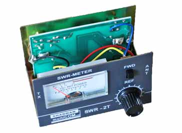
Directional coupler lines: There are several ways of creating the coupler lines. The most common way is probably to use a printed circuit board and to run the main match 50Ω line on the PCB with a ground plane on the other side. This creates a 50Ω line of the correct line width, PCB thickness, etc are used. The coupler lines can then be run alongside this. Internal view of an SWR bridge showing the PCB and coupler lines
Another way was to use semi-air-spaced coax. This had small cylindrical hollow pipes running through the dielectric to provide the semi-airspacing. Small wires could be run through a short length of this to provide the required pick-up.
Yet another method is to use torroidal pickups. These tend to have a much flatter response and enable the actual power levels to also be determined. The lines are frequency dependent.
I thought these products may be of interest . . . . . .
These SWR meters might be useful when looking into antennas, feeders and SWR:
NISSEI RX-103 Mini SWR/Watt Meter 2KW 1.6-60MHz
RS-103 can measure forward and reverse power, as well as SWR for AM, SSB, etc. Frequency range: 1.6 - 60MHz, Measurable power range: 1W up to 2KW.
Original Nissei Dg-503 Digital LCD 3.5" SWR & Wattmeter 1.6 - 60 MHz / 125 - 525 MHz
The digital meter can be used to measure forward power, reflection power and VSWR, 0 - 200W; 3.5 inches LCD display for easy reading; LCD backlight display, Forward / Reflective / VSWR Ratio in one push button.
A novel RF powered SWR meter with a frequency range from 3 - 30MHz. Although you would not want to leave this in circuit all the time because of the RF loss, it is able to provide a useful indication of SWR. Ideal for amateur radio enthusiasts to use in the field.
Note: We make a small commission from any sales at no cost to you.
SWR bridges are relatively low cost items, and they are often bought as kits or competed items. This enables the issues with creating the coupler lines to be overcome, and also the metalwork is normally provided, providing a high quality finish.
Written by Ian Poole . Experienced electronics engineer and author.


 Written by Ian Poole .

