Inductive Reactance Formula & Calculations
Any inductor resists the changes of an alternating current and this results in it presenting an impedance to it.
Inductance and Transformer Tutorial Includes:
Inductance
Symbols
Lenz's law
Self inductance
Inductive reactance calculations
Inductive reactance theory
Inductance of wire & coils
Mutual inductance
Transformers
An inductor resists the flow of an alternating current as a result of its inductance. Any inductor resists a change in current as a result of Lenz’s Law.
The degree to which the inductor impedes the flow of current is due to its inductive reactance.

The inductive reactance is frequency dependent – rising with frequency, but it can easily be calculated within straightforward formulas.
Inductive reactance
The effect by which the current flow of an alternating or changing current in an inductor is reduced is called its inductive reactance. Any changing current in an inductor will be impeded as a result of the inductance associated with it.
The reason for this inductive reactance can be simply seen by examining the self-inductance and its effect within the circuit.
When a changing current is applied to an inductor, the self-inductance gives rise to an induced voltage. This voltage is proportional to the inductance and as a result of Lenz's law the induced voltage is in the opposite sense to the applied voltage.
In this way the induced voltage will work against the voltage causing the current to flow and in this way it will impede the current flow and the inductor is said to have a certain inductive reactance.
Inductive reactance formulas
Although there is perfect inductors do not exist, it is helpful to imagine one to look at the formulas and calculations associated with inductors and inductance. In this case a perfect inductor is one that only has inductance, and no resistance or capacitance.
The inductive reactance of an inductor is dependent upon its inductance as well as the frequency that is applied. The reactance increases linearly with frequency. In other words, doubling the frequency will double the inductive reactance of a particular coil, wire, etc.
It is for this reason that at very high frequencies, the inductive reactive for lengths of wire become important and within some circuits, it is necessary to ensure that connections are kept as close as reasonably possible.
It is possible to express this as a formula to calculate the reactance at a particular frequency.
Where:
XL = inductive reactance on ohms, Ω
π = Greek letter Pi, 3.142
f = frequency in Hz
L = inductance in henries
Ohm's law and inductive reactance
If a changing signal such as a sine wave is applied to this perfect inductor, the reactance impedes the flow of current, and follows Ohms law.
If the only component present is the inductor, then it is simply a matter of applying Ohm's law and calculating the voltage or current, etc from a knowledge of the other two variables. It is also possible to calculate the reactance from a knowledge of the voltage and current.
Where:
XL = inductive reactance on ohms, Ω
V = voltage in volts
I = current in amps
It is possible to use the Ohm's law triangle. This is an easy method of memorising the equation for Ohm's law. Simple take the variable that is required to be calculated and

The triangle is used by covering up or highlighting the required variable. The remaining two can then be seen. If the two variables are next to each other, they are multiplied together.
If the variables are one above the other then the top one is divided by the bottom one. This can be summarised in the overall summary diagram of how the Ohm's law triangle can be ised for inductive reactance below.

Using the Ohm's law triangle in this way, enables the right calculations and formula versions to be used for inductive reactance when making Ohm's law style calculation.
Adding inductive reactance and resistance
A real inductor will have some resistance, or inductors may be combined with resistors to make a combined network. In either of these cases it is necessary to know the overall impedance of the circuit.
As the current and voltage within an inductor are 90° out of phase with each other (current lags the voltage), inductive reactance and resistance cannot be directly added.


It can be seen from the diagram that the two quantities need to be added together vectorially. This means that the inductive reactance and resistance each need to be squared, added and then the resultant square root taken:
This can be re-written into a more useable format:
The resultant combination of resistance and inductive reactance is referred to as impedance and this is again measured in ohms.
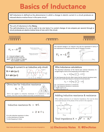
Basics of inductance infographic
I've created an infographic summarising some of the key aspects of self inductance: what it is and the basic formulas.

Click on image for larger version
When using and designing circuits that contain inductors it is often necessary to look at the inductive reactance, calculate it using the formulas above and then add this to a pure resistance to gain the overall impedance. As such these formulas are particularly useful.
 Written by Ian Poole .
Experienced electronics engineer and author.
More Basic Electronics Concepts & Tutorials:
Voltage
Current
Power
Resistance
Capacitance
Inductance
Transformers
Decibel, dB
Kirchoff's Laws
Q, quality factor
RF noise
Waveforms
Return to Basic Electronics Concepts menu . . .


