What is Mutual Inductance
Mutual inductance is an effect that can be important when varying currents are passing in wires or coils that are close to each other and it is the primary effect used in transformers.
Inductance and Transformer Tutorial Includes:
Inductance
Symbols
Lenz's law
Self inductance
Inductive reactance calculations
Inductive reactance theory
Inductance of wire & coils
Mutual inductance
Transformers
While the concept of self inductance is widely talked about within electrical and electronic circuit design, its cousin termed mutual inductance is probably a little less widely seen.
As the name indicates, mutual inductance is an effect whereby the currents from signals in one circuit can affect those in a nearby circuit or circuits.
Accordingly, not only is mutual inductance an effect that is essential for the understanding of components such as transformers, motors and generators, but it is also important in understanding some stray effects where nearby wires can be affected by stray pickup and the like.
In order that mutual inductance provides benefits in an electrical or electronic circuit, rather than introducing unwanted effects, it is essential to be able understand exactly what it is and how it occurs.
Basic understanding of mutual inductance
Mutual inductance occurs when the magnetic field associated with one wire or coil in one circuit cuts across the wire or coil of a second circuit.

If the current in the first circuit is changing, then the magnetic field created by the first circuit will change and in turn this will induce an electromotive force, EMF in the second circuit.
To accommodate Lenz's law, it is found that if any current flows in the second circuit, will then feed back into the first circuit causing the action of the second circuit to oppose that in the first.
The inductance of a single wire is relatively small, and to increase this, the wire can be made into the coil and this significantly increases the effect.
Similarly for mutual inductance. Therefore people often talk about the mutual inductance between two coils. But it is also necessary to remember in many areas of electronic circuit design, and particularly RF design, that mutual inductance is also present between wires or conductors.
To expand the concept of mutual inductance between two coils, take the example of two coils placed in close proximity so that the magnetic field generated by the first links through that of the second.
Mutual inductance definition
As mutual inductance is such a fundamental parameter within any electrical or electronic circuit, that it is necessary to define what it is and understand how it affects a circuit.
Mutual inductance definition:
Mutual inductance is a circuit parameter between two magnetically coupled circuits or coils is the effect whereby the time varying magnetic flux caused by the changing current in the first circuit causes an EMF to be induced in the second.
The units of mutual inductance, like inductance are measured in Henries. Again it is possible to define the Henry as it is a derived SI unit and has a standard definition associated with it.
The Henry definition:
The derived SI unit of electric mutual inductance is the Henry; the inductance of a closed circuit in which an EMF of 1 volt is produced when the current varies uniformly at the rate of 1 ampere per second.
This is very much the same as that of the Henry when used for self inductance. The only difference is that two coils are involved, but the same process occurs.
Mutual inductance with differently placed coils
It can be seen that a coil through which current is passing will create a magnetic field. This field can then interact with another coil placed near by.
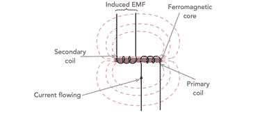
The primary winding - the one where the main input current is flowing, has a magnetic field set up around it. If there is a varying current in the primary, the a varying field will be created and any other wire or coil nearby will come under its influence and an EMF will be induced in it. But not for induction between one coil or wire and another, the current in the primary must be varying.

In order to maximise the linking between the two coils, they are often put right next to each other and on the same axis. In this way the field generated by the current flowing in the first coil will link better to the second coil.
Increasing the linking between the coils increases the mutual inductance and this is important for many applications.

It can be seen that the flux linkage between the two coils is not perfect because the flux from the first coil still spreads out and does not fully link with the second coil.
To considerably improve the flux linkage between the two coils, a ferromagnetic core can be added between the two coils. This ensures that virtually all of the magnetic flux from the first coil links to the second one. This considerably improves the efficiency of the assembly - often efficiency levels of transformers can exceed 95% or more.
Common materials used for these cores can be soft iron and a group of substances called ferrites.
There are also a variety of different formats for transformers using cores. Each one has its own advantages and disadvantages.
Mutual inductance calculations & equations
When using and investigating mutual inductance it is necessary to undertake various calculations.
The basic equation links the rate of current change with the mutual inductance and the induced EMF.
Where:
Em is the EMF induced in the secondary in volts
I1 is the current in coil 1 in amperes
t is the time in seconds
Using this equation it is possible to see that if the induced EMF is one volt and the rate of change of current is one amp per second, then the mutual inductance is one Henry.
Ways to increase mutual inductance
It is worth summarising the ways in which the mutual inductance between two or more coils can be increased. There are a few straightforward ways in which this can be done:
Increase turns on each coil: By increasing the number of turns on the coil, the magnetic flux can be increased and this will enable the other coils to be affected more by the magnetic flux. Similarly if the number of turns in the other windings are increased, then they become more susceptible tot he linked flux.
Decrease separation between the coils: Decreasing the separation between the coils helps because the further away they are the less is the magnetic field from the first coil.
Use a ferromagnetic core: The use of a ferromagnetic core on which all the coils are wound will significantly increase the flux and ensure that there is more linkage between the various coils.
Understanding mutual inductance in real circuits
When two or more coils are mutually coupled, it is found that when a changing current flows in one coil, this will produce a magnetic flux that will link to the other coupled coils. It will also couple to the first coil as well, so there is a level of mutual inductance to the other coils and self inductance for the coil with the varying current.
The other coils will also exhibit both self inductance and mutual inductance if a current flows in them as a result of the current in the first coil.
Hence there will be both a self-induced EMF and and a mutually induced EMF in each of the coils.
These effects can be explained using Faraday's law of induction which states that the magnitude of voltage is directly proportional to the rate of change of flux.
In this way the laws of physics remain constant wherever the effects are found.
Mutual inductance is a key parameter for any transformer where the level of mutual inductance enables an EMF to be induced in a second circuit when the current in the first circuit changes. This is a very useful phenomenon enabling transformers to operate, however mutual inductance can also occur between two wires and sometimes it can result in unwanted coupling between circuits giving spurious signals that are not wanted.
Understanding how mutual inductance occurs and how it can be sued is very helpful in understanding the operation of many electronic circuit designs.
 Written by Ian Poole .
Experienced electronics engineer and author.
More Basic Electronics Concepts & Tutorials:
Voltage
Current
Power
Resistance
Capacitance
Inductance
Transformers
Decibel, dB
Kirchoff's Laws
Q, quality factor
RF noise
Waveforms
Return to Basic Electronics Concepts menu . . .