
Eddystone EC10 Vintage Radio
The Eddystone EC10 was a transistorised broadcast communications receiver covering the MF and HF bands.
Eddystone Radio Receivers Includes:
Eddystone EA12
EA12 circuit description & block diagram
Eddystone EC10
Iconic radio receivers:
Summary of iconic radio receivers
Radio receiver history
Crystal radio sets
Development of the superhet radio
Radio history / timeline
The Eddystone EC10 was one of the first ventures into radios using semiconductor technology for Eddystone.
Having had a long and distinguished line of valve based communications receivers, many of which are now classic vintage radios, Eddystone needed to move forward into the semiconductor age.
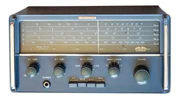
The EC10 was one of their first radios to be fully transistorised and was first seen in 1963, and as such was a leader at the time. Although it worked well and received many very positive reviews at the time, many agree that it did not have the performance of their previous valve / tube based radios, although later designs from the same stable considerably improved on the performance.
The EC10 was in many ways a ground breaking communications receiver - one of the first fully transistorised sets, and this makes it a classic vintage radio.
Eddystone EC10 overview
The Eddystone EC10 was one of the first professional radio receivers to use all transistor technology.
The circuit used a total of ten transistor, all of which were germanium as transistors using this semiconductor were far more widely available. Silicon transistors were not widely used until a little later.
In addition to the transistors, a total of three diodes were also used.
The construction for the radio was based around a printed circuit board, but there were still many techniques used that were common in the larger valve / tube radios. For example large screens were placed around the RF areas of the circuitry.
The radio covered frequencies from 550 kc/s up to 30 Mc/s in a total of 5 ranges. This meant that it was able to cover the medium wave broadcast band, short wave broadcast bands, marine and the MF & HF amateur radio frequencies as well.
In terms of the transmission of modulation modes that are catered for, the radio was aimed at CW and AM. As single sideband was particularly widely used, single sideband, SSB was not expressly catered for. However it was perfectly easy to use the CW position and adjust the BFO frequency accordingly.
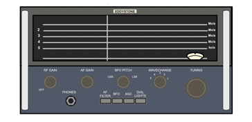
The radio incorporates independent RF and AF gain controls and in addition to this there are separate controls for the BFO ON/OFF and AGC switching. There is also a BFO pitch control as well.
In terms of the mechanical aspects of this vintage radio, it retained the Eddystone feature of having a very luxurious tuning feel to it. The tuning control was loaded with a flywheel and this was connected to a well engineered 110:1 reduction drive.
The main scale provided a total of nine inches of band-spread like many other Eddystone vintage radios. Coupled with the reduction drive, etc, this made tuning very easy and with a calibration accuracy of 1%, this enabled easy location of frequencies for its day.
A switch is provided for turning the dial illumination on and off - having the dial illumination off will preserve the batteries by reducing consumption.
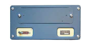
The radio was powered by six D cells or U2 using the terminology of the day. A separate battery compartment was used. If buying one of these vintage radios, care should be taken to ensure that old batteries had not been left in the battery compartment as this could cause serious damage to the circuit board, etc.
When operation of the EC10 was required from the mains, a suitable Eddystone power supply unit was available.
Eddystone EC10 brief specification
The specification for the EC10 vintage communications radio shows that it offered adequate performance for many requirements, but it did not have the really high levels of performance that the earlier valve / tube radios from Eddystone offered.
That said, the EC10 was one of the first communications radios to use transistor technology and at the time of its launch the transistor in use tended to be germanium types rather than silicon. This did limit some aspects of the performance.
| Brief Specification for the Eddystone EC10 Vintage Radio Receiver |
|
|---|---|
| Parameter | Specification |
| Basic description | Single conversion MF / HF superhet radio using transistors for the active devices. |
| Frequency coverage | The overall coverage is 550 kc/s to 30 Mc/s in five bands: |
| Intermediate frequency | 465 kc/s |
| Sensitivity | Better than 5µV for 15dB S/N ratio on bands 1 - 4 Better than 15µV on band 5 |
| IF selectivity | Typical overall bandwidths at -6dB and -40dB are 6 kc/s and 25 kc/s respectively |
| IF breakthrough | Ranges 1 - 4 greater than -85dB Range 5 greater than -65dB |
| Image rejection | 50dB at 2.0 Mc/s and 20 dB at 18.0 Mc/s |
Semiconductor line-up
The Eddystone EC10 had a total of ten transistor and five diodes in the circuit.
| Transistor Line-up for Eddystone EC10 Radio Receiver Circuit |
||
|---|---|---|
| Transistor Number | Type | Use within the EC10 circuit |
| TR1 | OC171 | RF amplifier |
| TR2 | OC171 | Mixer |
| TR3 | OC171 | Local oscillator |
| TR4 | OC171 | 1st IF amplifier |
| TR5 | OC171 | 2nd IF amplifier |
| TR6 | OC171 | Beat frequency oscillator |
| TR7 | OC71 | Audio amplifier |
| TR8 | OC83 | Audio driver |
| TR9 | OC83 | Audio output |
| TR10 | OC83 | Audio output |
In addition to the transistors themselves, the EC10 also had several semiconductor diode providing a variety of functions.
| Diode Line-up for Eddystone EC10 Radio Receiver Circuit |
||
|---|---|---|
| Diode Number | Type | Use within the EC10 circuit |
| D1 | OA70 | AGC attenuator |
| D2 | OA90 | Detector / AGC |
| D3 | OAZ203 | Voltage stabiliser |
| D4 | DD006 | Aerial protection diode |
| D5 | DD006 | Aerial protection diode |
Eddystone EC10 circuit description
The EC10 is a single conversion superheterodyne radio using a free running local oscillator. It used a total of ten transistors in the circuit as well as five semiconductor diodes. The topology for the radio was very standard as it used a single down-conversion to the 465kc/s local oscillator and it had a simple diode envelope detector for AM and a beat frequency oscillator is provided for CW reception which could also be used for SSB - SSB was not widely used when the EC10 was first introduced.
The input to the EC10 circuit is provided via tuned RF transformers - one for each band which are switched in to circuit as needed. A series trap tuned to the intermediate frequency is introduced on the high frequency band to provide rejection of the IF frequency, preventing direct IF break-though.
The first transistor is TR1 which is connected in a grounded base configuration as this provides a low input impedance and current gain suitable for this stage. The grounded base configuration also provides RF stability as the grounded base tends to isolate the input and output circuits.
The RF gain control along with the AGC voltage is applied to the base voltage of TR1, reducing the gain as required.
The output of this stage passes through another tuned RF transformer to improve image rejection and this is applied to the mixer stage built around TR2. There is one for each band, switched in as appropriate. A low impedance link from the RF transformer provides the required low impedance for the circuit.
The transistor TR3 acts as the local oscillator and has a tuned collector circuit. Its output is directly connected to the mixer circuit.
The supply for all three of the RF stages is provided via an OAZ203 voltage reference diode. It provides a nominal 6.5 volts to these stages. Having the voltage supply for all three of these stages regulated ensures the best frequency stability.
The IF amplifier stages are based around two transistors: TR4 and TR5 along with five tuned circuits tuned to the intermediate frequency of 465 kc/s.
The AGC and RF gain control act on the first stage of IF amplification, reducing the gain as required to prevent overload, etc. The second stage operates at a constant gain.
An interesting additional automatic gain facility is added to the first IF transformer. The diode D1 is used as a switch to introduce a damping resistor across the primary of the transformer, reducing the Q of the circuit and adding further gain reduction. It prevents overloading of the second IF stage and the detector stage.
The diode D2 is a germanium OA90 and this provides the detector function for the radio. It is actually housed inside the last IF transformer and as well as providing the signal demodulation, a feed is also taken to be filtered accordingly to provide the signal level for the AGC.
For CW reception the beat frequency oscillator based around TR6 is introduced. the output from this stage is fed into the last IF stage and enters the detector along with the signal. The non-linear action of the detector diode enables the beat frequency from the incoming CW signal to create an audio signal. The mixing process also allows for SSB reception as well. Adjustment of the BFO frequency via the front panel control enables the right beat note or SSB audio to be obtained with the signal centred around the middle of the passband. The BFO supply voltage is regulated using a separate stabilised source using the Zener diode, D3
The audio from the detector is amplified using a first stage of amplification based around TR7. It then passes from here though a switchable audio filter that provides audio selectivity for CW reception. It then passes into an audio friver stage based around TR8.
The final stage of audio amplification is provided by two OC83s, TR9 & 10 operating in class B, push pull. This gives the high level output sufficient to drive the internal output loudspeaker. Alternatively there is the option for an external speaker as well.
The Eddystone EC10 represented a major step forward in communications receiver technology. It was one of the first communications receivers to use transistors, although being an early adopter of semiconductor technology, the devices used tended to be germanium types. Also the performance was not up to that of previous valve / tube types, or those semiconductor based radios that were designed when better devices were available.
There were some significant advantages to the use of semiconductor technology in radios. For the EC10, they were mainly in terms of size, power consumption and convenience. They set was primarily powered using internal batteries, although an external supply could be used if needed.
 Written by Ian Poole .
Experienced electronics engineer and author.
More History:
Radio history timeline
History of the radio
Ham radio history
Coherer
Crystal radio
Magnetic detector
Spark transmitter
Morse telegraph
Valve / tube history
PN junction diode invention
Transistor
Integrated circuit
Quartz crystals
Classic radios
Mobile telecoms history
Vintage mobile phones
Return to History menu . . .


