
EA12 Circuit Description & Block Diagram
The Eddystone EA12 followed a straightforward format for a double conversion superheterodyne radio and was able to provide a high level of performance.
Eddystone Radio Receivers Includes:
Eddystone EA12
EA12 circuit description & block diagram
Eddystone EC10
Iconic radio receivers:
Summary of iconic radio receivers
Radio receiver history
Crystal radio sets
Development of the superhet radio
Radio history / timeline
Although the basic circuits and block diagram for the Eddystone are not revolutionary in using new technology, they utilise some very sound engineering techniques and enable the very high levels of performance for the receiver. It is the quality of the overall engineering, circuit design and performance that make the Eddystone EA12 a classic radio receiver
The radio communications receiver, does employ a number of techniques that may seem unusual, especially today when techniques like digital signal processing and software defined radio technology are the norm.
Overall, the circuit for the radio communications receiver provides the controls that are needed, an overall high level of performance and a feel of real luxury when using it.
Valve line-up
The Eddystone EA12 circuit uses a total of thirteen valves or vacuum tubes within the receiver. These are all the modern small valves using either B7G or B9A valve bases.
The line up of valves / vacuum tubes for the EA12 circuit can be seen int he table below.
| Valve Line-up for Eddystone EA12 Radio Receiver Circuit |
||
|---|---|---|
| Valve Number | Type | Use within the circuit |
| V1 | ECC189 | RF amplifier |
| V2 | ECH81 | 1st mixer & 1st local oscillator amplifier / doubler |
| V3 | EC90 | 1st oscillator |
| V4 | ECH81 | 2nd mixer and 2nd oscillator isolation amplifier |
| V5 | EC90 | 2nd local oscillator |
| V6 | EF93 | 1st 100 kc/s IF amplifier |
| V7 | EF93 | 2nd 100 kc/s IF amplifier |
| V8 | EB91 | AM detector and AGC rectifier |
| V9 | ECC83 | Cathode follower and audio amplifier |
| V10 | EK90 | CW / SSB product detector |
| V11 | EL90 | Audio output amplifier |
| V12 | 150C2 | HT voltage stabiliser |
| V13 | EF94 | Crystal calibrator oscillator |
The valves or vacuum tubes used in the EA12 circuit are relatively common, and even now they can be obtained without too much difficulty, although these days vacuum tubes or valves are not as widely available as they were.
High level circuit and block diagram overview
The EA12 receiver consists of a double conversion superhet with a crystal controlled first conversion to convert the signal down to a variable first IF stage.
This is followed by a second mixer controlled by a variable frequency oscillator to convert the signal to the second and fixed intermediate frequency.
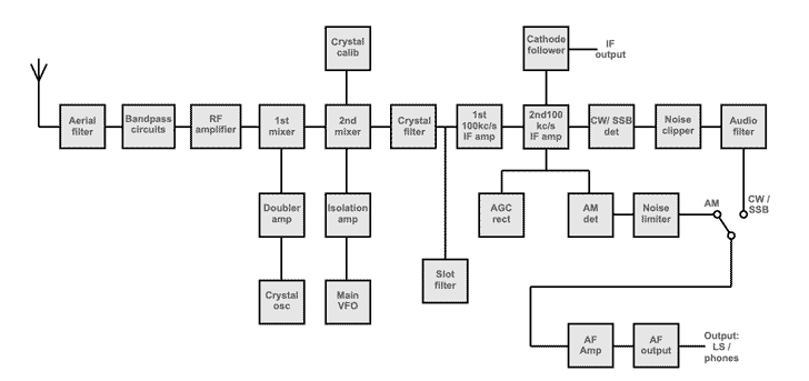
The use of this type of configuration enables the variable frequency local oscillator to run at a low frequency and not have to be switched, both of which factors give improved stability.
In addition to this, the higher frequency of the first IF enables better image rejection to be obtained.The second IF has variable selectivity and this can be selected according to the mode in use or as conditions suit.
Then the signal can be detected using an envelope detector for AM or a product detector for CW or sideband. There is also a detector for the AGC whose output acts on both the RF and IF stages.
The audio signal is amplified and is available for driving either an internal or external loudspeaker or headphones.
Although this line-up may sound as if it is fairly conventional for a receiver of its day, a closer look reveals that there are several unusual and interesting features embedded in the circuit design, making a closer look at the circuitry very worth-while.
EA12 RF circuits
The signals from the antenna enter the receiver and they first pass into a high-pass filter to stop breakthrough from the aerial to the first IF. This may not seem to be particularly important, but there are many strong signals present within the range of the first IF and these are attenuated by 90dB or more.
The signals also pass through a bandpass circuit to reduce image and prevent the RF amplifier from being overloaded by the additive effect of the huge number of signals present over a wide bandwidth.
Having been filtered the signal passes into the first RF amplifier. This consists of a double triode valve in a cascode configuration. This not only gives a good cross modulation performance, which will be of interest to anyone keen on operation on 7MHz, but also gives a better noise performance than a pentode.
Frequency conversions
Leaving the RF amplifier, the signal is then passed into the first mixer stage, which converts the signal down to the first intermediate frequency.
This mixer is driven by a crystal oscillator. The actual oscillator operates at half the required frequency and it is then doubled using a frequency doubler stage before being presented to the first mixer stage.
The first IF lies between 1.1 and 1.7MHz and is surprisingly low as many other designs favour 9MHz, yet it still enables the image rejection to be quoted at 50dB for the highest frequencies and proportionally better for the lower ones.
However, the choice of this low IF does enable the variable frequency oscillator to be run between 1.0and 1.6MHz, which is low and leads to good stability.
The circuit of this oscillator is where one of the unusual design features can be seen. Contrary to normal practice, the VFO HT voltage is not stabilised. The explanation given in the manual says that any variation in the mains voltage will result in fluctuations in both the HT and the heater voltages, both of which will affect the frequency of the oscillator. However, it is said that they act in opposite directions and therefore tend to cancel one another out. This fact seemed to be borne out in practice as the receiver was perfectly stable over a long period.
Using this VFO the signal is converted down to the second IF of 100kHz which, although it is not standard, does allow fo LC filters to be used where other receivers would use a selection of crystal or mechanical filters.
Fixed IF stage and filters
The fixed IF stage consists of two amplifier stages (V6 & V7 - 2 x EF93)) that are coupled using IF transformers. These provide the basic adjacent channel selectivity for the radio.
The two valves act as pentode amplifiers and have the AGC line which reduces the gain for strong signals.
The main selectivity of provided by a total of seven tuned circuits in the IF stages. The selectivity is varied by mechanically moving the secondary coils in three IF transformers. By changing the coupling, it enables the selectivity to be varied continuously from 6kHz to 1.3kHz (at 6dB) which is an unusual feature in itself. There are positive "stops" for the 1.3kc/s and 3kc/s settings which are marked CW and SSB respectively
A further narrowing of the selectivity is brought about by switching in a single close tolerance crystal to give a 50Hz band-width.
In addition to all of this there is a notch filter capable of giving a sharp 40dB notch, which can be very useful to remove annoying carriers on either CW or sideband.
Signal detection
The signal detection stages follow a relatively classic format for communications radios.
The AM detector uses a diode detector and then a filter to remove the RF and then the signal is passed to a noise limiter to remove very high level clicks and bangs that may result from static and switching spikes that may be received.
For CW and SSB, a product detector is used. The signal from the BFO along with the IF output are mixer together to provide the required audio output. This is then clipped to remove any high level transients from static or other switching noises.
Interestingly the BFO and product detector are included in a single valve. This might be thought to be a bit of a compromise, but it works well, even on strong signals.
The AGC detector uses a diode detector. The output from this is fed through a CR network which can be switched to give the required time constant for AM, CW or SSB. The resulting output is then used as the AGC line to control the RF and IF stages, reducing the gain for suitably strong signals.
Audio stages
Once the audio has been generated it is then passed through an audio filter whose bandwidth is set for the mode in use. While no filtering is used on AM, on SSB or CW a filter is introduced which gives a 30dB fall in response at 5kHz. This can remove much of the annoying high frequency 'monkey chatter'.
In addition to this there is a further position which can be used for copying CW under difficult conditions which switches in a 300Hz wide bandpass filter centred on 1kHz. This can be used on its own or in conjunction with the crystal filter when conditions become really bad.
After the filters the signal then passes into the audio pre-amplifier, which is followed by an output pentode. This amplifier develops a maximum output of about 2.5 watts, which should be more than adequate for most people.
Crystal calibrator
There is also a crystal calibrator included in the receiver which generates 100 kc/s markers. The output from the calibrator is injected into the second mixer and the second IF.
Therefore, with the BFO switched off, a beat can be heard between the two signals. The manual says that it is unnecessary to inject the calibrator into the first mixer as this is crystal controlled and it is unlikely to need calibrating.
A small adjuster is placed above and to the side of the main dial to give the required calibration adjustment for the radio receiver.
EA12 construction
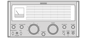
In keeping with the Eddystone style of construction the EA12 is very sturdily built. Both the coil box and front panel are cast and the remainder of the receiver is built to a similar standard. This does mean that the whole receiver is quite heavy, weighing around 47 lbs, which means that even though it is not as heavy as some of the classic communications of the 1940s it is still not a piece of portable equipment!
Internally the layout is well set out, enabling easy servicing, and in addition to this the standard of construction is high, which should mean that it will only occasionally require attention. These points are particularly important in a receiver of this age because unreliability or difficulty in servicing could leave the receiver off the air for long periods.
The Eddystone EA12 is a classic radio receiver of the mid 1960s. The quality of the engineering, build and the performance made it a real luxury radio to use. Although the performance of the filters may not compare to a good modern crystal filter, the overall radio performance was very good, especially for its day. This made it a classic radio for ham radio use.
 Written by Ian Poole .
Experienced electronics engineer and author.
More History:
Radio history timeline
History of the radio
Ham radio history
Coherer
Crystal radio
Magnetic detector
Spark transmitter
Morse telegraph
Valve / tube history
PN junction diode invention
Transistor
Integrated circuit
Quartz crystals
Classic radios
Mobile telecoms history
Vintage mobile phones
Return to History menu . . .


