
Eddystone EA12 Ham Band Radio Communications Receiver
The Eddystone EA12 was a classic radio communications receiver for ham radio dating from the 1960s but offering a very high level of performance.
Eddystone Radio Receivers Includes:
Eddystone EA12
EA12 circuit description & block diagram
Eddystone EC10
Iconic radio receivers:
Summary of iconic radio receivers
Radio receiver history
Crystal radio sets
Development of the superhet radio
Radio history / timeline
The Eddystone EA12 radio communications receiver was a classic radio of its day being available from around 1961 to 1969. It was an amateur or ham band only receiver covering the six pre-WARC bands below 30 MHz.
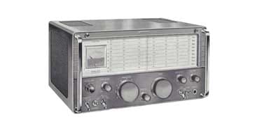
The Eddystone EA12 was considered by many to be a "Rolls Royce" of receivers - it was a classic radio communications receiver. It offered a very high level of performance but was one of the last of the really high quality valve or tube based radios that was manufactured.
Mechanically the EA12 was built to a very high standard, and as a result it was a relatively heavy item when compared to some of the other amateur radio equipment on offer at the time, but even so it was not nearly as heavy as the older receivers like the RCA AR88, etc.
Eddystone EA12 specifications
From the specification of the Eddystone EA12 radio communications receiver, it can be seen that it offers a high specifications, even by today's standards in many respects.
It does not offer all the bells and whistles of a modern radio communications receiver, and the shape factor of the filters is not as good as that of a modern set, but despite this, the radio could perform very well even under adverse conditions.
| Brief Specification for the Eddystone EA12 Radio Receiver |
||||||||||||||||
|---|---|---|---|---|---|---|---|---|---|---|---|---|---|---|---|---|
| Parameter | Specification | |||||||||||||||
| Basic description | Double conversion superhet radio communications receiver with crystal controlled first local oscillator covering the pre-WARC79 amateur radio / ham radio bands up to 30 MHz. | |||||||||||||||
| Frequency coverage | The HF ham radio bands are covered in nine separate 600 kHz bands: |
|||||||||||||||
| Antenna input | 75Ω unbalanced via Belling Lee coaxial socket | |||||||||||||||
| Sensitivity | 2µV for 10 dB signal to noise ratio for amplitude modulation in 6 kc/s bandwidth 0.5 &Micro;V for a 20dB signal to noise ratio with an IF bandwidth of 1.3 kc/s for CW. |
|||||||||||||||
| Frequency stability | Drift does not exceed 100 c/s in any hour after adequate warm up period. Short term drift is unlikely to exceed 20 c/s. A variation of ± 5% in mains voltage does not affect the tune frequency by more than 100c/s | |||||||||||||||
| Intermediate frequencies | 1.1 - 1.7 Mc/s and 100 kc/s | |||||||||||||||
| 2nd IF filter techniques | Crystal filter, slot filter, continuously variable filter using variable LC coupling | |||||||||||||||
| Tuning mechanism & scales | The EA12 uses a gear driven flywheel loaded tuning mechanism. It has a reduction ratio of 140 : 1. The scales are 10½ inches long. | |||||||||||||||
| Selectivity |
|
Image rejection | Better than 50 dB at highest frequency and proportionally better at lower frequencies | |||||||||||||
| IF breakthrough | Breakthrough attenuation at the first intermediate frequency is greater than 100dB except at 2 Mc/s on Range 9 where it is between 90 and 100 dB. At the second IF, breakthrough attenuation is better than 100dB. | |||||||||||||||
| Dimensions | Width: 16¾ Height 8¾ Depth: 13⅝ | |||||||||||||||
| Weight | 47 lbs (21.3 kg) | |||||||||||||||
EA12 front panel
The appearance of the EA12 is dominated by the large tuning scale and the two main control knobs for band-change and tuning. These give the radio communications receiver its distinctive look.
The left-hand knob provides the the band change capability, and the right-hand one is used for tuning the receiver. It is geared to give a reduction ratio of 140:1. This means that the tuning of sideband and CW signals is particularly easy and has a nice sense of band-spread. Whilst this is true, the downside is that it can take a long time when tuning from one end of a band to the other end.
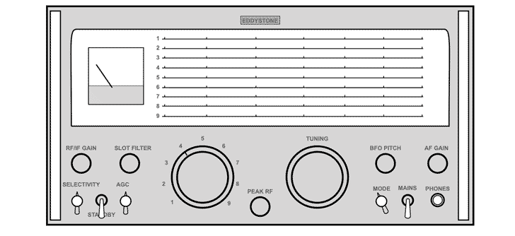
As already mentioned the tuning scale is long - it is a total of 10.5 inches and it is calibrated every 10kHz. This means that frequencies can be read to within a kilohertz or so, which is quite adequate for most purposes, although sometimes stations may give an exact frequency when changing frequency, etc, and the EA12 does not have a digital readout like many modern sets.
At the left-hand end of the tuning scale is the S-meter. This is a good size and it is calibrated in S units from S1 to S9 and then directly in dBs above S9.
The S meter appears to be relatively accurate from on-air tests and it responds well to signals large and small.
The main receiver controls are all found underneath the tuning and band-switch knobs. At the left-hand end of the panel are the RF and IF gain controls. These are mounted concentrically and they are used to give the optimum performance under any particular conditions, and particularly where strong signals are present. However, it is normally quite sufficient to use just the RF gain control except for very strong signals when both can be used, but in any case this is a matter of personal preference.
Next to these gain controls is the slot filter. When not in use this control is left in the fully counter-clockwise position. In this position the slot falls outside the passband of the receiver and therefore it has no effect. However, turning it clockwise makes the slot transverse the passband so that it can remove the unwanted carrier. This filter can be very useful, giving a sharp notch anywhere within the passband to remove unwanted carriers or heterodynes without unduly affecting the wanted received signal.
Underneath the gain and slot filter controls is located a switch for the filter bandwidth, standby and AGC / noise limiter controls. The one main drawback of the front panel design is that these are rather cramped. The left-hand control alters the selectivity. This is rather unusual in that it provides a continuously variable adjustment of the selectivity, although there are click stops for the standard bandwidth for each mode.
The crystal filter is also selected using this switch by turning the control slightly further than the CW position. This operates a microswitch that brings in the crystal filter for very narrow band reception for CW.Next to this is the standby switch which can be used manually to mute the receiver, or if it is left in the standby position this function can be controlled remotely by transmitter. Alternatively this switch can be used to control the transmitter via a connection on the rear panel.
Rear panel
The back of the EA12 radio communications receiver is reserved for connections and present controls that do not need to be changed during normal operation. On the back panel, there are three rectangular access holes cut in the outer case which give access to the connectors and controls which are mounted on the rear of the receiver chassis.
Looking at the back of the receiver the left-hand cut-out contains the mains input and fuse. There is also an S-meter zero preset control.
Next to this is the 'MUTE LEVEL' preset control. This adjusts the muting of the receiver when it is in the standby position. This is used for when the receiver is used in conjunction with a radio transmitter for two way radio communications. It enables the level of the transmitted signal received by the EA!2 to be adjusted for monitoring purposes.
The next access cut-out contains an earth point and the antenna or aerial input. Unfortunately the socket for this is one of the old Belling Lee TV types, unless it has been modified. These Belling Lee connectors would never be used nowadays they were in common use in amateur radio equipment back in the 1960s.
The right-hand cut-out reveals six connectors of various types. Two of them carry the speaker output and this can either be connected to the internal speaker via wires that come out from the case, or an external loudspeaker can be used if required.
Next to the speaker output is another Belling Lee coax socket. This carries a buffered IF output. This is very convenient for driving any ancillary units that may need an IF output. One possible application is for an external FM detector for use on 10 metres of for use with a 2 metre converter, etc. However, it should be noted that even in the AM selectivity position the IF may be rather narrow for perfect FM demodulation.
Below these are three connectors labelled RELAY, MUTE and AGC, which are for muting the receiver when it is used in conjunction with a transmitter. The first is intended to control a relay or PTT type line in the transmitter and in fact consists of a contact on the STANDBY switch which is shorted to ground when the switch is in the standby position.
The second is intended to be controlled by the transmitter, and with the switch permanently in the standby position uses a transmitter relay contact to short the terminal to ground for receive.
Finally, the third contact is intended for use with valve controlled transmit / receive switches which were popular in the 1960s. This terminal should normally be at earth potential for receive, but when the receiver is to be muted a voltage of about -50 volts should be applied. The exact voltage can be varied slightly to give the correct degree of muting for monitoring the transmission.
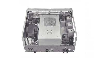
Eddystone EA12 circuit overview
The Eddystone EA12 featured a double conversion superhet format using a crystal controlled first oscillator to convert to a first IF of 1.1 - 1.7 Mc/s and then a second oscillator running on the low side of the signal between 1.0 and 1.6 Mc/s. With this second variable oscillator running at such a low frequency, the stability is really good.
The second IF is at 100Kc/s and it features some innovative filtering. provides continuously variable selectivity, with some set bandwidths that can be used for AM, SSB, and CW. This is achieved by varying the coupling between the IF transformers.In addition to this there is a variable notch filter that can be used to remove an unwanted signal.
Detection uses a diode for AM, and a product detector for CW and SSB. The product detector uses a penta-grid valve that functions as a product detector and high stability oscillator.
Once demodulated the signals pass through a diode noise limiter to remove any high level spikes and then can pass through an audio filter.
The audio is amplified and then passed to an internal speaker, external speaker if present or headphones.
A crystal calibrator is also present to ensure that the receiver is on frequency. It generates a 100 kc/s signal that can be picked up across all frequencies.
The EA12 includes its own mains power supply. This uses silicon diodes to give full wave rectification.
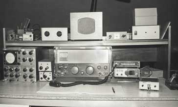
The Eddystone EA12 was a delight to use - it is one of the few radios that I have owned that I now regret selling on, although I must admit it was rather large and heavy. When it was being used, it had the feel of real luxury. It performed well, it had superb band-spread and tuning and it was straightforward to use. The downsides were that it was getting older, it was very heavy and large by today's standards and the some areas of the performance could not compete with a modern radio, especially in terms of selectivity where the inductor filtering gave a poorer shape factor than that which can be obtained with a high performance crystal filter or digital signal processing filters. Nevertheless it was certainly a classic radio of its time which can still give a good account of itself today.
 Written by Ian Poole .
Experienced electronics engineer and author.
More History:
Radio history timeline
History of the radio
Ham radio history
Coherer
Crystal radio
Magnetic detector
Spark transmitter
Morse telegraph
Valve / tube history
PN junction diode invention
Transistor
Integrated circuit
Quartz crystals
Classic radios
Mobile telecoms history
Vintage mobile phones
Return to History menu . . .


