
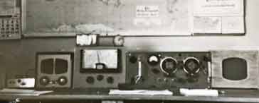
KW-Geloso Receiver Front End Converter
The KW-Geloso receiver front end converter is little known these days, but in the late 50s and early 60s it provided an ideal way of proving ham band coverage.
KW Amateur Radio Equipment Includes:
KW Electronics
KW-Geloso Front End Converter
KW2000 transceiver
KW204 transmitter
Iconic radio receivers:
Summary of iconic radio receivers
Radio receiver history
Crystal radio sets
Development of the superhet radio
Radio history / timeline
The KW-Geloso front end receiver converter is very rarely seen these days, but in the 1950s and 1960s when government surplus equipment was the main source of equipment for radio amateurs, it provided an ideal way of gaining good performance for the amateur radio HF bands.
For many of the government surplus radios, performance on many of the HF amateur radio bands was limited. Coverage for some of these vintage radios stopped around 20 MHz, and where it did extend, the band-spread was exceedingly poor making operating very difficult on these frequencies.
To overcome these issues Geloso produced a front end module and KW added other essentials like the overall chassis, power supply and case. Initially this was sold as a kit, but ready built versions were also available.
(The 19set had the transmitter disabled so there was no chance of putting tranmitter power into the output of the receive converter)
Concept of the KW-Geloso converter
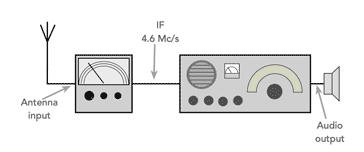
The concept behind the KW-Geloso converter was simple. The main radio would be tuned to the fixed IF frequency of 4.6 Mc/s from the converter. The main receiver would then effectively provide the IF for the overall receiver with IF filtering, detection and audio amplification, etc.
The KW-Geloso converter would provide the front end capabilities. It had good band-spread on all the HF amateur bands of the day from 80 metres to 10 metres. Being a more modern design, it would also be more likely to offer better stability at the higher frequencies. Another advantage was using a high intermediate frequency of 4.6 Mc/s, it would provide excellent image rejection.
Also the converter would be likely to improve the sensitivity, especially at the higher frequencies because more modern valves were sued than those int he older surplus radios.
Using the KW-Geloso converter in front of the existing radio created a double conversion superhet, making it quite advanced for the day.
Details of the KW-Geloso converter front end
There did not appear to be a formal specification available for the KW Geloso front end. It was available form Geloso, or it could be bought from KW.
The Front end using was used int he Geloso G207-DR double conversion superhet vintage radio, and also as this separate unit.
The unit consisted of a few sections including the coil unit, dial and escutcheon, slow motion drive with knobs, etc and the gang condenser as it was called then.
The basic kit in its original form only needed external connections to HT, LT, condenser, IF transformer, AVC and antenna.
Two types of IF transformer were available fort he output - one for the case where it was used within an receiver where it was connected directly to a mixer, and another where it was to be used with another receiver and connected tot he antenna input - this would require a low impedance connection.
| KW-Geloso Converter Frequency Coverage |
||
|---|---|---|
| Band Number | Amateur Radio Band (Metres) | Frequency Coverage (Mc/s) |
| A | 80 | 3.5 - 4.0 |
| B | 40 | 6.95 - 7.6 |
| C | 20 | 13.8 - 14.6 |
| D | 15 | 20.6 - 22.0 |
| E | 11 | 26.4 - 28.1 |
| D | 10 | 28.0 - 29.8 |
The dial mechanism provided a 72:1 reduction which enabled a luxurious amount of band-spread to be achieved for the day. It made tuning in single sideband signals much easier.
The overall dial mechanism had a fine fibreglass cord contained ina nylon sleeve which was claimed to be long lasting ad providing a very smooth action in operation - which I confess I remember it did.
Circuit summary
the circuit for the KW-Geloso receiver front end converter was quite straightforward. It would not have been out of place in many amateur radio receivers of its day - as already mentioned it was used in the Geloso G207-DR.
Essentially the unit consisted of an RF amplifier which took its input from the antenna. The output from this was fed into a mixer along wi the local oscillator signal to give an output at 4.6 Mc/s for the main receiver to pick up.

The RF amplifier was quite straightforward utilising a 6BA6 pentode. Being a pentode it offered good RF stability as the screen and suppressor grids isolated the anode from the control grid.
The antenna was connected to a trap tuned to 4.6 Mc/s to eliminate any signals that might break though to the IF. IT was then passed into the switched tuned transformers and applied to the grid of the 6BA6.
The output was then applied to the input of the 6BE6 mixer via further tuning to ensure that out of band signals do not enter and affect the performance.
The local oscillator was based around a 12AU7 double triode. The first half of this was used as the oscillator. The oscillator frequency was controlled by a section of the ganged variable capacitor to ensure all tuned circuits tracked together. The inductors were switch for each band by the overall band switch.The second half of the 112AU7 was used as a buffer. This prevented any loading effects from the RF amplifier or mixer from affecting the oscillator frequency. Also by loading it less, frequency stability was improved.
The mixer used a 6BE6 valve. It took in both signal and local oscillator signals. Its output was via a 4.6 Mc/s tuned IF transformer. There were options for a low impedance output (used fort he case of the converter, or a higher output impedance if the RF unit was to be used within an overall receiver and the output was to be applied to a second mixer.
Power requirements for the coil pack were +210 volts for the amplifier and mixer and 150 volts stabilised for the oscillator and its buffer. A 6.3V AC supply was also needed for the valve heaters.
For the unit from KW, the power supply was included within the unit and used a VR150 stabilised, a double diode for full wave rectification and the relevant mains transformer, etc.
Although these units are rarely seen on the market today, and their existence is mostly forgotten, in the late 1950s, the provided an ideal way for radio amateurs to be able to utilise the main receivers they had in a far better way. The KW Geloso converter provided improved gain and sensitivity, band-spread to properly cover the amateur bands, and improved stability over the majority of receivers that would have been available and affordable at the time.
Most of the receivers were the vintage radios that we see today, and they did not have the HF performance that might be needed. Accordingly the KW-Geloso converter was an ideal addition to many radio stations.
 Written by Ian Poole .
Experienced electronics engineer and author.
More History:
Radio history timeline
History of the radio
Ham radio history
Coherer
Crystal radio
Magnetic detector
Spark transmitter
Morse telegraph
Valve / tube history
PN junction diode invention
Transistor
Integrated circuit
Quartz crystals
Classic radios
Mobile telecoms history
Vintage mobile phones
Return to History menu . . .


