
KW2000 Amateur Radio Transceiver
The KW2000 was an HF amateur band vintage radio communications transceiver capable of handling 90w or 180W PEP input on the existing HF bands of the time.
KW Amateur Radio Equipment Includes:
KW Electronics
KW-Geloso Front End Converter
KW2000 transceiver
KW204 transmitter
Iconic radio receivers:
Summary of iconic radio receivers
Radio receiver history
Crystal radio sets
Development of the superhet radio
Radio history / timeline
The KW2000 series of amateur radio transceivers was produced mainly in the 1960s by KW Electronics based in Dartford Kent. In view of its age, the KW2000 is now certainly deemed to be a vintage radio.
The KW2000 was popular in the UK and was used by a very large number of radio amateurs in the UK and countries with associations to the UK. A few found their way to the USA, but with other popular manufacturers there, they never managed to penetrate the market much.
The KW2000 was said to have been the UK's attempt to compete with the Collins KWM2 and a number of parallels can be seen between the two pieces of radio communications equipment.
The transceiver certainly managed to be a much more compact HF transceiver than might have previously been available, and it certainly was a very successful piece of amateur radio communications equipment.
Story of the KW2000
During the 1950s and early 1960s, most amateur radio stations used separate transmitters and receivers. Also in the late 1950s and early 1960s single sideband started to take over from amplitude modulation for AM long distance radio communications.
A number of companies were still producing AM / CW transmitters, but there was a growing demand for single sideband equipment. Often home building this equipment was beyond the reach of many radio hams who may not have had the time, expertise and test equipment required to build an SSB transmitter or transceiver.
KW was set up in the 1950s and steadily built up its reputation starting with antennas and then moving on to AM/CW separate transmitters and receivers and finally producing some SSB transmitters.
With the launch of the Collins KWM2 in the USA, there was obviously a need for a more cost effective solution for use in the UK and beyond.
Seeing this need, KW set about developing a compact HF transceiver. It was at the Radio Communications Exhibition in 1963 that KW announced their KW2000 transceiver. It covered all the amateur bands of the time between 160 metres and 10 metres (160, 80, 40, 20, 15, & 10).
The cabinet design represented a significant change from the rather chunky designs of the post war years to a new sleek and more modern design of the sleeve with rounded corners. In many ways it had many similarities to the far more expensive KWM2 from Collins in the USA.
Over the years the KW2000 evolved and several versions were launched.
| Versions of the KW2000 Vintage Radio Transceiver for HF Amateur Radio Bands |
|
|---|---|
| Version | Highlight details and Updates |
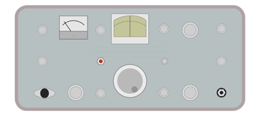
| KW2000 | Launched in 1963, the original transceiver covered the HF ham bands in 200 kc/s sections, and had a PA used a single 6146 with a maximum input of 90W PEP and 45 - 50W PEP output. |
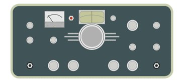
| KW2000A | This introduced an updated styling and colour scheme with a dark blue-grey front panel. Technically it had an updated PA that utilised 2x6146 to give 180W PEP DC input to the final RF amplifier. This would represent an output power of around 100 W PEP. |
| KW2000B | A version that was introduced around 1969. It incorporated a few updates to improve the performance including a new dual speed drive that enabled more convenient tuning. |
| KW2000C | This was a version that was intended for commercial usage and it had four crystal controlled channels. |
| KW2000D | This was a digital development that provided for a digital readout, but it was never produced on a commercial basis. |
| KW2000E | This was the last major update and it introduced 500 kc/s bands to remove the necessity for changing bands for the complete coverage of an amateur radio allocation that was more than 200 kc/s wide. |
With the take-over of KW by Decca, little additional development was undertaken and the KW2000 line ceased production in the 1970s. The KW2000 had been a very successful development, a vast number of these transceivers were produced as they offered a very affordable but capable transceiver when little else comparable was on the market for the right cost for many radio amateurs.
Their popularity started to fall as the first Japanese offerings appeared on the market. As the new Japanese offerings had a worldwide market, development could be more easily justified and their performance rose whilst costs fell.
Today, a number KW2000 transceivers appear in the vintage radio markets or within the amateur radio magazines. They can still perform well on the bands providing a good basis for amateur radio communications, but they naturally lack many modern requirements like computer control, digital readouts, digital frequency setting and readout and the like that modern radio communications equipment offers.
Brief specification for KW2000
the KW2000 was the base transceiver upon which all the later variants were based. The specification below is for the original KW2000.
| Brief Specification for the KW2000 Vintage Radio Transceiver |
|
|---|---|
| Parameter | Specification |
| Basic description | Double conversion superhet radio communications radio communications transceiver with crystal controlled first receiver local oscillator covering the pre-WARC79 amateur radio / ham radio bands up to 30 MHz. |
| Frequency coverage | 1.8 - 2.0; 3.5 - 3.7; 3.7 - 3.9; 7.0 - 7.2; 14.0 - 14.2; 14.2 - 14.4; 21.0 - 21.2; 21.3 - 21.5; 28.0 - 28.2; 28.4 - 28.6; 28.6 - 28.8 Mc/s |
| Microphone input | High impedance |
| Transmitter power | SSB: 90 watts PEP, CW 75watts (note: this is the PA input power). |
| Sideband suppression | Better than 45dB |
| Carrier suppression | Better than 50dB. |
| Receiver sensitivity | better than 1µvolt for 17dB S/N |
| IF selectivity | 2.1kc/s at -6dB; 6kc/s at -60dB. |
| Audio output | 2 watts into 3Ω |
| Dimensions | 13 ¾" x 5⅞" x 10 ½" deep |
| Weight | Approx 16 lbs; AC PSU: 20 lbs; DC PSU: 6½ lbs |
The initial KW2000 had a single 6146 that enabled it to deliver around 45 - 50W output PEP from a DC PA input of 90 W input. The KW2000A and later models utilised two 6146s to double the power capability.
KW2000 valve line-up
The KW2000 has a complement of 20 valves or tubes providing all the active devices within the set.
| Valve Line-up for KW2000 Vintage Radio Communications Transceiver for Amateur Radio |
||
|---|---|---|
| Valve Number | Type | Use within the circuit |
| EF183 | Receiver RF amplifier | |
| 6BE6 | 1st Mixer - receiver | |
| 6BE6 | 2nd Mixer - receiver | |
| 6BA6 | 1st IF amplifier - receiver | |
| 6BA6 | 2nd IF amplifier - receiver | |
| 6AL5 | AVC rectifier | |
| 12AX7 | Product detector & tone oscillator | |
| ECL82 | AF amplifier and power output | |
| 6146 | RF power amplifier | |
| 6CL6 | RF PA driver | |
| 12AT7 | 2nd Mixer - transmitter | |
| 12AT7 | 1st Mixer - transmitter | |
| 6AM6 | Crystal oscillator | |
| EF183 | IF amplifier - transmitter | |
| 12AT7 | Beat frequency oscillator | |
| 6U8 | Variable frequency oscillator | |
| 12AX7 | Microphone amplifier | |
| 12AT7 | "S" meter amplifier | |
| 12AU7 | Cathode follower | |
In addition to the valves there are two diodes used for the balanced modulator used for the SSB generation.
KW2000 circuit overview
Within the circuit there is a lot of re-use of circuits between transmit and receiver. This enables the number of valves to be kept to a minimum. That said different receiver and transmitter IF and mixers are different. However elements like the mechanical filter required to provide the receiver selectivity and filtering of the transmitter signal to remove the unwanted sideband are the same.
Transmitter: Looking at the transmitter signal flow, the audio from the microphone enters the microphone amplifier. This uses the two halves of a 12AX7 to bring it to the required level. The tone oscillator used to generate the CW tone is after the first half of the amplification.
The output from audio amplifier is then applied to the VOX amplifier as well as a cathode follower that drives the balanced modulator. The balanced modulator is used because it suppresses the carrier on the output creating a double sideband suppressed carrier signal.
The oscillator for the BFO for demodulating the received signals as well as generating the carrier signal for the transmitter is based around a 12AT7 with switched crystals for upper and sideband.
The signal is passed into the transmitter IF amplifier and then through the mechanical filter which removes the unwanted sideband to create the required single sideband signal.
Once filtered the single sideband signal enters the first transmitter mixer. This mixes with the local oscillator and generates the IF signal in the band 2.955 to 3.155 Mc/s.
A second mixer uses the output from the switched crystal oscillator to bring the signal to the required output frequency.
The signal is then amplified in the 6CL6 driver and this signal is then passed into the 6146 final amplifier. It then passes through the transmit receive switch to connect to the antenna.
Receiver: For the receiver, the antenna passes through the transmit receive switch straight into the EF183 that provides the RF tuning and amplification.
From here, the signal passes directly into the first receive mixer consisting of a 6BE6. This takes its oscillator input from the switched crystal oscillator to provide an output at the first IF between 2.955 and 3.155 Mc/s. This provides filtering to remove out of band signals.
The signal is then applied to the second receiver mixer consisting of another 6BE6. Here it is mixed with the variable local oscillator to bring the signal down to the final IF at 465 kc/s. ItAt the IF the signal is first passed through the mechanical filter to give the required bandwidth, and then it is amplified using two transformer coupled receiver IF stages, each using a 6BA6.
The output from this stage is passed into the AGC detector whose output is applied to the RF and IF stages and also used to drive the S meter. The IF signal is also passed into the product detector which is driven by the BFO / carrier oscillator.
The resulting audio is passed into the ECL82 which provides the audio amplification and audio power output.
An output is also taken from the triode audio amplifier stage to provide the "ANTI-VOX" which prevents the receive audio activating the VOX facility.
 Written by Ian Poole .
Experienced electronics engineer and author.
More History:
Radio history timeline
History of the radio
Ham radio history
Coherer
Crystal radio
Magnetic detector
Spark transmitter
Morse telegraph
Valve / tube history
PN junction diode invention
Transistor
Integrated circuit
Quartz crystals
Classic radios
Mobile telecoms history
Vintage mobile phones
Return to History menu . . .


