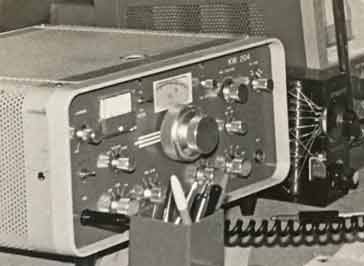
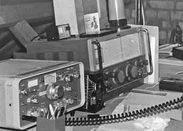
KW204 Transmitter
The KW204 transmitter was an HF amateur band transmitter capable of delivering around 100 W PEP output from two 6146 valves / tubes.
KW Amateur Radio Equipment Includes:
KW Electronics
KW-Geloso Front End Converter
KW2000 transceiver
KW204 transmitter
Iconic radio receivers:
Summary of iconic radio receivers
Radio receiver history
Crystal radio sets
Development of the superhet radio
Radio history / timeline
The KW204 was the last separate HF SSB / CW transmitter designed by KW Electronics. It essentially adopted the transmitter elements from the KW2000B, but was contained within a G-Line case and had its own integral power supply.
Running two 6146 valves in the final, it had a final DC input power level of around 180 watts PEP, and this gave around 100 watts PEP output. This enabled the transmitter to provide global amateur radio communications using a good antenna.
The KW204 was a reliable transmitter that was used by many who already had a receiver that they liked and wanted the flexibility of having "separates."
As the transmitter was pre-WARC 79, it only included the traditional HF amateur radio bands from 160 metres through to 10 metres.
KW204 transmitter basics
The KW204 was a convenient transmitter to use, having sufficient controls for successful operation without having a very cluttered front panel.
The circuit for the KW204 was quite straightforward and int he years since its launch in the early 1970s it has proved to be a reliable transmitter, and many are still in use to this day.
The transmitter did not over-stress components such as the RF PA final valves - some other designs used TV line output valves that could take short duration peaks, but cold not tolerate high duty cycle operation. Accordingly the PA valves tended to have a much longer life than those used in some other transmitters and transceiver.
The KW204 provided a good specification which compared well with those from other manufacturers and at the time the cost was quite competitive, especially for those in the UK where the transmitter was built.
KW204 transmiter specification
The specification for the KW204 was provided in the technical handbook as well as other marketing material from the company.
| Brief Specification for the KW204 Vintage Radio Transmitter |
|
|---|---|
| Parameter | Specification |
| Summary | All band (pre-WARC '79) amateur radio transmitter. |
| Modulation types | SSB, CW, AM |
| Frequency coverage | The KW204 transmitter covered all HF amateur bands of the time from 160 metres up to 10 metres in 500 kHz segments. 160 metres: - 1.8 - 2.3 MHz 80 metres: - 3.5 - 4.0 MHz 40 metres: - 7.0 - 7.5 MHz 20 metres: - 14.0 - 14.5 MHz 15metres: - 21.0 - 21.5 MHz 10 metres: - 28.0 - 28.5 MHz 10 metres: - 28.5 - 29.0 MHz 10 metres: - 29.0 - 29.5 - 2.3 MHz 10 metres: - 29.5 - 30.0 MHz |
| DC power input to final RF power amplifier | SSB - 180 watts PEP CW - 150 watts AM - 75 watts |
| Power output | SSB - 100 watts PEP nominal |
| Output impedance | 52 / 75Ω with SWR 2:1 |
| Microphone impedance | High impedance |
| Audio frequency response | 300 - 2500 Hz at -6dB |
| Carrier suppression | 50dB |
| Unwanted sideband suppression | 45dB |
| Third order distortion | -30dB |
| Power input | 117V or 234V ±5% at 45 - 65 Hz |
| Power consumption | Approximately 320 watts on transmit |
| Weight | 27 lbs |
In addition to this the advertising material advertised that there was the capability for an additional VOX unit to be added, ALC was present to ensure splatter was minimised and that the set had "silky smooth tuning."
KW204 valve line-up
The valve line up within the KW204 consisted of 11 valves and there were also 19 semiconductor diodes.
The valves are the "miniature types" with B7G and B9A bases with the exception of the much larger final amplifiers that use a form of Octal base.
| Valve Line-up for KW204 Vintage Radio Communications Transmitter |
||
|---|---|---|
| Valve Reference | Type | Use within the circuit |
| V1 | 12AX7 | Microphone amp & tone osc. |
| V2 | 12AT7 | Audio cathode follower & carrier oscillator | V3 | EF183 | 455 kHz amplifier |
| V4 | 12AT7 | 1st mixer |
| V5 | 12AT7 | 2nd mixer |
| V6 | 6CH6 | PA driver |
| V7 | 6146 | RF power amplifier |
| V8 | 6146 | RF power amplifier |
| V9 | 6U8 | Variable frequency oscillator |
| V10 | 6AM6 | HF crystal oscillator |
| V11 | OA2 | Voltage stabiliser |
KW204 transmitter circuit description
The KW204 has a fairly traditional block diagram and the circuits are relatively standard - few surprises to be had when looking at the way it works. However this has meant that the circuit is reliable and works well, as the basic circuit has bene updated from previous designs including the KW2000, KW Vespa, etc.

The signal chain started with the audio input. This is stage used half of a 12AX7 double triode. It provided a high input impedance to the microphone allowing ceramic and other similar microphones to be used along with the lower output dynamic microphones.
The output from the second stage of audio amplification passed into a cathode follower audio buffer stage.
The carrier oscillator is provided by the triode of a 12AX7. This is a crystal controlled oscillator and two crystals are used, one for USB and the other for LSB.
The audio and carrier oscillator are applied to a single balanced modulator or mixer consisting of two semiconductor diodes. Balancing the mixer properly enables the carrier level to be suppressed sufficiently.
The output from the balanced modulator was passed into an EF183 pentode amplifier. This not only amplified the signal level but also acted as a buffer after the balanced modulator, providing a much more consistent load impedance for the balance modulator.
After the EF183 amplifier, the signal entered the 455 kHz sideband filter - a Kokusai mechanical filter. This removed the unwanted sideband as well as providing a little extra carrier attenuation.
The signal required converting from the fixed IF up to the final operating frequency. This was accomplished in two stages. The first stage mixed the IF single sideband signal with the variable frequency oscillator to convert the signal up to the broadband IF of between 2.655 and 3.155 MHz. A 12AT7 double triode was configured as a balanced mixer for this.
The second frequency conversion used a crystal oscillator fed into a second 12AT7 double triode balanced mixer circuit. One crystal was used for each band to give the correct output frequency.
Once through all the conversions, the signal was amplified, first to provide an intermediate power level using a 6CH6 to give sufficient power to drive the two 6146 output power valves.
To generate CW and introduce carrier for AM, a small amount of carrier at the base intermediate frequency was introduced into the grid of the first mixer. This gave a much better CW note than the audio oscillator that was used in the KW2000
The KW204 was a popular transmitter at the time and it provided excellent service in many amateur radio stations. Being around 50 years old now, it can certainly be termed a piece of vintage radio equipment, but it can nevertheless perform well, even on today's amateur radio bands.
 Written by Ian Poole .
Experienced electronics engineer and author.
More History:
Radio history timeline
History of the radio
Ham radio history
Coherer
Crystal radio
Magnetic detector
Spark transmitter
Morse telegraph
Valve / tube history
PN junction diode invention
Transistor
Integrated circuit
Quartz crystals
Classic radios
Mobile telecoms history
Vintage mobile phones
Return to History menu . . .