
National HRO Communications Radio
The National HRO vintage radio was first introduced in 1935 and was widely used by allied forces in the World War II: then it became a favourite with many radio amateurs.
National Radio Receivers Includes:
National HRO
Iconic radio receivers:
Summary of iconic radio receivers
Radio receiver history
Crystal radio sets
Development of the superhet radio
Radio history / timeline
The National HRO is a vintage radio communications receiver that was introduced in 1935 and became a classic HF radio that performed well and was widely available in the surplus equipment markets for many years.
The HRO vintage radio was designed and manufactured by National Radio Inc based in Malden Massachusetts, USA, and was originally intended for both military and amateur radio communications usage.
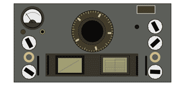
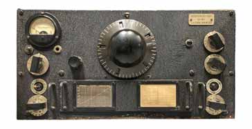
The HRO has two features that make it instantly recognisable. The first is the large epicyclic tuning dial that is located in the upper central part of the front panel.
The second is the coil packs at the bottom centre of the front panel - the HRO radio used different luggable coil-packs instead of having a vast set of switched coils for the RF section.
The National HRO vintage radio was very successful because although it was first launched in 1935, versions were still being manufactured until the 1960s.
National HRO development and history
The development of the National HRO vintage radio receiver can trace its origins to a contract that was awarded to the US General Electric Company (GE). The contract was for GE to provide the US Government's Bureau of Air Commerce with short wave transmitters and receivers.
At that time GE had no experience in designing and building radio receivers and therefore they enquired whether National Radio Company might be able to work with them and design the radio.
The design for the new radio was a 1.5 - 20 MHz superheterodyne radio. The radio was called an Air Ground Station, AGS, receiver and it used pluggable coil-packs and used a total of nine valves or tubes and it used a 500 kHz IF.
The radio was not perfect and the airlines who used them required a radio with better image rejection, improved selectivity and an automatic volume control (as the AGC was referred to in those days).
The airlines who used the radios submitted their own specification and National Radio designed a new receiver. This one also used the concept of pluggable coil sets and introduced the now famous epicyclic tuning dial.
The design for the radio was finished in 1934, and despite the best efforts of the company and all the tool-makers, etc, it was not possible to start production until 1935.
In view of the speed at which the company wanted to start production, the radio was known by the initials HOR (Hell or a Rush). The company did not want the radio to be known by the initials HOR as this would easily be associated with the word whore. Accordingly they transposed the letters to HRO - Hell of a Rush Order and the name stuck!
This vintage radio was widely used in WW II. Not only was it used in the USA, but also in the UK where over 10 000 units are estimated to have been shipped, many being used by the Y Stations that intercepted Nazi radio communications that were then sent on to Bletchley Park.
The radio was widely used after the war, being updated many times and the final production occurred in 1964. It was used in a number of professional radio communications applications, as well as by radio amateurs.
National HRO models & variants
Many thousands of HRO radios were made over the years of its production. Coupled with extended time over which HROs were manufactured, it is not surprising that a large number of variants appeared.
A list of most of the different HRO variants is given in the table below.
| HRO Version | Details | Year introduced |
|---|---|---|
| HRO | This was the original version of the HRO. IT was renamed the HRO Senior (Snr) when the HRO Junior was introduced | 1934/5 |
| HRO-SPC | Rackmount version of the HRO | |
| HRO-B | Version of the HRO intended for battery operation. | |
| HRO-JR | HRO Junior. This was a low cost version of the HRO without items like the crystal filter, S meter, etc. It also lacked the band-spread option capability of the HRO Senior and was normally used with coil sets JA, JB, JC and JD. Typically only one coil set was supplied wit the radio. | 1936 |
| HRO-M | This was probably the most common model of the HRO and it was widely used for British Y Stations that intercepted the Nazi communications. | 1941 |
| HRO-MX | 1942 | |
| HRO-5 | This was an upgraded version of the HRO-M and was gradually introduced into WW2 operations including those associated with Bletchley Park. It was updated version of the HRO, but using octal valves. | 1944 |
| HRO-W | Version of the HRO for the US Signal Corps | |
| HRO-5A | Post War version of HRO-5 | |
| HRO-60 | This was the last version of this vintage radio and was manufactured between 1952 and 1964. | 1952 |
In addition to the versions of the HRO manufactured by National Radio, copies were also manufactured by a number of other companies, including some in Nazi Germany and Japan in the war years.
National HRO frequency ranges & coil packs
The National HRO radio receiver used pluggable coil packs to provide the switching between different ranges. This considerably reduced the size of the actual radio receiver itself and also improved the reliability and performance because each coil pack cold be optimised for its band and there were the long leads often needed when arranging switched coils were removed. In particular the problem of signal losses associated with large switched front ends was removed.
The different coil packs enabled operation from frequencies as low as 100 kHz right up to 54 MHz.
| Coil-Pack Ref | Frequency Range | Band-spread |
|---|---|---|
| A | 14 - 30MHz | 10 Metres |
| B | 7 - 14 MHz | 20 Metres |
| C | 3.5 - 7.3 MHz | 40 Metres |
| D | 1.7 - 4 MHz | 80 Metres |
| E | 0.9 MHz - 2.05 MHz | |
| F | 500 - 1000 kHz | |
| G | 175 - 400 kHz | |
| H | 100 - 200 kHz | |
| J | 50 - 100 kHz | |
| AA | 27.5 - 30 MHz | |
| AB | 25 - 35 MHz | |
| AC | 21 - 21.5 MHz | |
| AD | 50 - 54 MHz | |
| JA | 14 - 30MHz | 1s |
| JB | 7 - 14.4 MHz | |
| JC | 3.5 - 7.3 MHz | |
| JD | 1.7 - 4 MHz |
Coil pack types A to D have a band-spread capability on the amateur radio bands mentioned. These particular HRO coil-packs or coil units had two frequency ranges. In one mode the coil covered a wide frequency range, i.e. general coverage, while in the other mode, known as band spread, serial and parallel capacitors were added to reduce the coverage to approximately the width of an amateur band.
Note that types A to D and JA to JD have similar coverage values, however it is only coil sets A to D that have the amateur band band-spread.
National HRO performance specification summary
The National HRO had an impressive performance specification for its day. The HRO specification may not appear to be that good by today's standards, but it must be remembered that the superhet radio had only been in widespread use for a very few years at this time.
| National HRO Performance Summary |
|
|---|---|
| Parameter | Details |
| HRO summary | Single conversion superhet covering 100 kHz to 54 MHz dependent upon the coil packs available. |
| Frequency bands | See the details of the coil packs. |
| Reception modes | CW, MCW |
| Antenna input | Suitable for use with transmission line, doublet antenna, or a single wire antenna. The antenna input impedance averages 500 Ω at frequencies higher than 1700 kc/s. |
| Intermediate frequency | 455 kHz |
| Selectivity | Crystal filter off: approximately 3 kc/s at two times down Crystal filter in broad position approximately 2.5 kc/s Crystal filter in sharp position approximately 200 cycles. |
| Dimensions | |
| Weight | |
| Power requirements | The receiver is designed for use with an external power unit capable of supplying 240 volts DC at 70 milliamperes and 6.2 volts AC at 3.4 amperes although lower plate supply voltages down to 135 volts may be used wit the sacrifice of some performance. |
Radio operation
As this is a vintage radio, some controls may not be familiar to those more sued to using modern radio communications equipment.
Coil sets: One of the first features is that the band changes are undertaken by changing the coil set that is located in the lower centre portion of the front panel. The coil packs or coil sets have handles to enable them to be pulled out of the radio. When a different one is installed it should be pushed firmly home.
There are different coil packs for different bands as detailed in a table above.
Tuning dial: The most unusual feature is the tuning dial and its calibration.
The dial is arranged so that the frequency increases with clockwise turns of the dial. Calibration marks on the dial and the numbers in the slots give the number that can then be used with a calibration chart on the coil set to give the frequency.
The RF gain located in the lower right hand corner of the vintage radio adjusts the amplification of both the RF amplifier stages, preventing overload of later stages of the radio when strong signals are present.
Coil set change switch: Just above the RF gain control, there is a toggle switch that is used to shut the receiver down when changing the coil sets. It controls the HT for the set, and can also act as a mute switch when the receiver is used with a transmitter.
Phasing control: The phasing control and crystal filter switch is located immediately above the coil change / mute switch. When the control is rotated to the "0" position the crystal filter is disconnected. Then for settings between 1 and 10 the crystal filter is in circuit and the phasing control balances the filter to remove the interfering signals.
Selectivity control: The selectivity control is located on the front panel of the HRO above the phasing control. When the crystal filter is in use the minimum selectivity will be found with the pointer nearly vertical and at this point the background noise will fall - this is not surprising since the noise power is proportional to the bandwidth.
When the crystal filter is not in use, the control acts as an IF trimmer and should be adjusted for maximum output from the receiver.
CW Osc: This controls the beat frequency oscillator for the HRO receiver. IIf the control is rotated in a clockwise direction it will cause HT to be applied to the BFO valve / tube and start it to operate. Rotation of the control between 0 and 10 varies the frequency of the oscillator across the intermediate frequency passband. This allows the BFO or CW oscillator to be set to give the required beat note with the signal entered in the passband.
AVC: The AVC switch is located above the CW Osc control. It enables the AVC to be turned on when t is required. It was typically expected that the AVC would be off for the reception of CW.
Audio Gain: The audio gain control is self explanatory - it controls the volume for the radio and can be set to give the required audio level out.
National HRO vintage radio circuit description.
The circuit for this vintage radio receiver followed the design lines for the day. It must be remembered when looking at the circuit, that this communications radio was designed only a few years after the superhet radio was allowed to be manufactured by companies apart from the Radio Corporation of America after they lost a lawsuit in 1930. Previously RCA had complete control over the superhet patent.
The HRO circuit included two RF amplifiers, a mixer with separate local oscillator and this was followed by two RF amplifier stages.
This vintage radio communications receiver then included a diode envelope detector for MCW (and also AM but this was not mentioned in the original documentation), and a product detector for CW (and later SSB, although again this was not mentioned in the documentation as SSB was not used when this radio was designed).
| Valve Line-up for National HRO Vintage Radio Communications Receiver |
||
|---|---|---|
| Valve Number | Type | Use within the circuit |
| V1 | 6D6 | 1st RF |
| V2 | 6D6 | 2nd RF |
| V3 | 6C6 | First detector (mixer) |
| V4 | 6C6 | High frequency oscillator |
| V5 | 6D6 | 1st IF |
| V6 | 6D6 | 2nd IF |
| V7 | 6B7 | Diode detector, AVC, first audio |
| V8 | 42 | Second audio |
| V9 | 6C6 | Beat frequency oscillator |
• RF amplifiers and tuning: Within the HRO there are two stages of RF amplification based around two 6D6 valves (in the original design - later versions used more modern valves). Accompanying these amplifiers there are three sets of tuned circuits to give good image rejection. These tuned circuits all track together as a result of the use of a four gang variable capacitor (the fourth section is used for the HF oscillator).
The amplifier stages have been designed to offer a good level of gain flatness over the whole range. This was something of an issue in radios of the era - these vintage radios often suffered from a reduction in gain at higher frequencies.
• HF oscillator: The HF oscillator is based around a 6C6 pentode valve. The circuit uses a Hartley form of circuit and this utilises the attributes of the valve to give the optimum performance. Not only does it limit the effect of any variations in the anode or plate circuit back to the tuned circuit of the oscillator, but the output has a much lower content of harmonics that would give rise to unwanted mix product and spurious signals.
Careful attention was given during the design to the stability of the oscillator. Temperature compensating capacitors were added to the coils to ensure that the drift was minimised.
• RF mixer: This stage is also referred to as the first detector in the early literature about the radio. This mixer stage of the radio is based around a 6C6. The mixer is capacity coupled from the cathode of the oscillator. This approach was adopted to reduce the pulling of the oscillator by the mixer and also to reduce the number of harmonics from the oscillator that might cause spurious signals to be received.
The first mixer converts the signals dow from the incoming frequency down to the intermediate frequency of 455 kHz.
• IF amplifier and filter: As already mentioned, the IF is at a frequency of 455 kHz and it comprises two amplifier stages each based around a 6D6.
All the interstage coupling uses tuned IF transformers. The coupling from the mixer also has the crystal for the crystal filter. There is a switch for this to be bypassed if a wider filter setting is needed.
Using the crystal, filter bandwidths down to 200 Hz (200 c/s) can be achieved and there are switches to give a selection of selectivity settings which can be used according to the prevailing reception conditions.
• Signal detector: The signal detection s provided by a double diode triode valve. This not only acts as the signal detector, but also the AGC detector and first audio amplifier.
• Audio output: The audio output is provided by a Type 42 valve which is an output pentode.. This provides a maximum of 2 watts output into a 7000Ω load or 1.5 watts undistorted.
• Beat oscillator: Also known as the CW oscillator this provides the beat signal for the CW (Morse) and it is injected into the signal chain just prior to the diode detector. The frequency of the oscillator can be adjusted to give the required beat note once the station has been tuned to the centre of the passband.
The National HRO is one of the classic vintage radio communications receivers. Although it was first launched in1934 / 1935, the radio was in use by many government organisations well after World War II, and by many radio amateurs and short wave listeners until the 1960s and 1970s.
This vintage radio provided coverage over a very wide range, provided the coil packs were available. Although the coil packs took up considerable space, the basic radio was much smaller than other radios like the AR88 and others that did not have external coil packs.
 Written by Ian Poole .
Experienced electronics engineer and author.
More History:
Radio history timeline
History of the radio
Ham radio history
Coherer
Crystal radio
Magnetic detector
Spark transmitter
Morse telegraph
Valve / tube history
PN junction diode invention
Transistor
Integrated circuit
Quartz crystals
Classic radios
Mobile telecoms history
Vintage mobile phones
Return to History menu . . .


