RCA AR88 Circuit Description & Block Diagram
Circuit description and explanation along with a block diagram for the RAC AR88 vintage radio communications receiver.
RCA AR88 Radio Receiver Includes:
RCA AR88
AR88 circuit description & block diagram
Iconic radio receivers:
Summary of iconic radio receivers
Radio receiver history
Crystal radio sets
Development of the superhet radio
Radio history / timeline
The AR88 electronic circuit design was undertaken with the aim of providing a cost no object high performance receiver for radio communications reception.
The electronic circuit design provided a circuit that offered very high level of performance for the day and as such provided a very useful radio receiver capability for the exacting requirements for monitoring and other applications during World War II.
The circuit was designed to provide the best possible performance and in this it succeeds in many ways, and although rather heavy it was used by radio enthusiast for many years afterwards.
Valve / tube complement
The RCA AR88 circuit used a total of 14 valves or vacuum tubes in the circuit, and unlike some other radios of the day, the mains power supply was incorporated within the radio itself and did not need an external box for this.
| Valve Line-up for RCA AR88 Radio Receiver Circuit |
||
|---|---|---|
| Valve Number | Type | Use within the circuit |
| V1 | 6SG7 | 1st RF amplifier |
| V2 | 6SG7 | 2nd RF amplifier |
| V3 | 6J5 | Oscillator (receiver local oscillator) |
| V4 | 6SA7 | Detector (receiver frequency changer / mixer) |
| V5 | 6SG7 | 1st IF amplifier |
| V6 | 6SG7 | 2nd IF amplifier |
| V7 | 6SG7 | 3rd IF amplifier |
| V8 | 6H6 | 2nd detector & AVC |
| V9 | 6H6 | Noise limiter |
| V10 | 6SJ7 | 1st audio amplifier |
| V11 | 6K6GT | Power output (audio output) |
| V12 | 6J5 | Beat frequency oscillator |
| V13 | VR150 | Voltage stabiliser |
| V14 | 5Y4GT | Double diode mains rectifier |
AR88 circuit block diagram overview
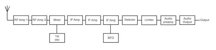
The diagram below shows that block diagram for the AR88 radio communications receiver.
The block diagram shows that AR88 is a single conversion superhet radio receiver. This was the main format used for the day, multiple conversion superhets tended to be introduced later.
There are three stages of IF application at the intermediate frequency of 455 kc/s, after which the signal is detected or demodulated using a diode detector. The BFO is introduced into the final IF stage.
An audio limiter is provided to reduce the effects of local static noise and this is followed by an audio preamplifier and final output amplifier.
AR88 RF circuits
The RF section of the AR88 circuit consists of two stages of RF amplification, each based around a 6SG7 pentode valve.
To provide the required tuning of these stages a four gang variable capacitor is required - three for the RF tuning, and the fourth for the local oscillator.
The antenna input to the receiver is designed to accept 200&Omega line, although an unbalanced input also appears on the circuit.
There are tuned circuits for the input of the first stage, the interstage coupling and the output which is fed into the mixer. The first tuned circuit is provided with a trimmer to optimise the signal.
The amplifiers have been designed to minimise effects like blocking and cross modulation that can occur when very strong signals are present.
Another major consideration during the electronic circuit design for the radio was the noise contribution from these stages. They have been designed to ensure to provide the optimum noise performance.
AR88 mixer circuit
The mixer, or frequency changer is referred to in the manual as the first detector. It takes the RF input from the RF amplifiers along with the local oscillator signal an converts them to change the frequency of the incoming signal to the 455 kc/s frequency of the IF stages.
The local oscillator runs on the high side of the incoming signal, and it is based around a 6J5 triode valve.
AR88 first heterodyne oscillator
This oscillator may be more commonly termed the first local oscillator these days. It runs 455kc/s higher than the signal frequency.
The circuit is based around a 6J5 triode valve. The inductors have been wound to provide a high Q for oscillator stability and the overall mechanical arrangement has been made sturdy, again for stability.
To provide a stable voltage for the oscillator, a VR150 voltage stabiliser is used. This will protect the oscillator from variations in line voltage that would otherwise change the operating voltage on the oscillator.
Intermediate frequency crystal filter circuit
The output from the frequency changer circuit is fed directly into a crystal filter that can be switched in or out.
The anode of the first mixer circuit is tuned and a balanced circuit is used to couple the mixer to the first IF amplifier input. A 455 kc/s crystal is connected in one am of the link and a neutralising capacitor is used in the other arm.
The impedance of the coils are such that they do not make the filter excessively sharp and in fact the filter characteristic can be adjusted to give bandwidths of 400 c/s, 1500 c/s and 3000 c/s.
AR88 intermediate frequency amplifier circuits
The AR88 circuit includes tree stages of IF amplification. Each stage uses a 6SG7 valve / vacuum tube.Interstage coupling uses tuned IF transformers. The first IF transformer has its primary and secondary circuits tuned and it is coupled through the crystal filter link.
The second and third IF stages have transformer which have a total of four tuned circuits. The coupling between the two windings in each transformer can be varied to alter the selectivity, and this is arranged using the selectivity switch.
The AGC line is only connected to the first and second stages in the IF (as well as to the RF stages). The third IF is also not linked tot he gain control and this enables good overload performance to be achieved.
The Beat frequency oscillator is coupled to the grid circuit of the third IF. This circuit arrangement allows the BFO coupling to be minimised for frequency stability whilst also providing sufficient injection.
AR88 circuit for AGC
The voltage needed for the AGC line is obtained from what is termed the second detector, i.e. the demodulator circuit. It is based around the 6H6 diode valve / vacuum tube.
The front panel control allows for the selection of the required AGC time constant as different time constant are needed for AM and CW.
One important factor os that the BFO injection level is such that it is just below the level that would cause the AGC to act. In this way it does not affect the operation of the AGC.
Audio circuits
The audio enters a noise limiter. This employs diodes to clip the audio to reduce the level of any static or other transients that may be received. The level can be set to suit the prevailing conditions.
The audio is then passed to V10, a 6SJ7 pentode as the audio preamplifier. The output from this stage is then passed to a 6K6GT which acts as the power output.
The output valve operates into an output transformer that enables it to match into a 2.5Ω loudspeaker, 600Ω load or into headphones.
Terminals are provided on the rear panel for the loudspeaker, and the 600Ω line. A headphone socket is provided on the front panel for when phones are to be used.
AR88 power pack circuit.
The power supply for the AR88 is quite straightforward. It uses a mains transformer to give the high tension, HT as well as 6.3 V AC for the valves and 5 V AC for the rectifier.
The centre tapped HT winding enables the two diodes in the rectifier to give full wave rectification for improved ripple and hum suppression.
The rear panel provides a "tap switch" for selecting the required input voltage.
Smoothing is provided a Pi section filter using two inductors. The output line is used for the HT line and it is also fed via a dropper resistor to the VR150 voltage stabiliser to give a stabilised 150 V line to power the local oscillator.
The AR88 circuit provides a fairly standard format for the circuit of a radio communications receiver of the day. However, the design and construction were optimised to ensure the best performance possible.
Even years later, the AR88 was looked upon as a top quality receiver that was able to provide reliable performance under difficult reception conditions.
 Written by Ian Poole .
Experienced electronics engineer and author.
More History:
Radio history timeline
History of the radio
Ham radio history
Coherer
Crystal radio
Magnetic detector
Spark transmitter
Morse telegraph
Valve / tube history
PN junction diode invention
Transistor
Integrated circuit
Quartz crystals
Classic radios
Mobile telecoms history
Vintage mobile phones
Return to History menu . . .