
Oscilloscope Probes Explained
Oscilloscope probes are an essential element of any oscilloscope test, providing the means to probe and interface to the circuit, and their performance is crucial to the final test result.
Oscilloscope Tutorial Includes:
Oscilloscope basics
Oscilloscope types
Specifications
USB vs bench-top scope
How to use an oscilloscope
Scope triggering
Oscilloscope probes
Oscilloscope probe specifications
Scope probes include:
Oscilloscope probes
Probe compensation
Oscilloscope probe specifications
Oscilloscopes are one of the main test instruments used for the development, test and repair of electronics equipment of all types.
However it is necessary to have a method of connecting the input of the oscilloscope to the point on the equipment under test that needs monitoring.
To connect the scope to the point to be monitored it is necessary to use screened cable to prevent any pick-up of unwanted signals and in addition to this the inputs to most oscilloscopes use coaxial BNC connectors.
While it is possible to use an odd length of coax cable with a BNC connector on one end and open wires with crocodile / alligator clips on the other, this is not ideal and purpose made oscilloscope probes provide a far more satisfactory solution.
Video: oscilloscope probes
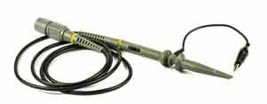
Oscilloscope probes
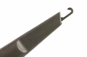
Oscilloscope probes normally comprise a BNC connector, the coaxial cable (typically around a metre in length) and what may be termed the probe itself. This comprises a mechanical clip arrangement so that the probe can be attached to the appropriate test point, and an earth or ground clip to be attached to the appropriate ground point on the circuit under test.
Care should be taken when using oscilloscope probes as they can break. Although they are robustly manufactured, any electronics laboratory will consider oscilloscope probes almost as "life'd" items that can be disposed of after a while when they are broken. Unfortunately the fact that they are clipped on to leads of equipment puts a tremendous strain on the mechanical clip arrangement. This is ultimately the part which breaks.
X1 and X10 oscilloscope probes
There are two main types of passive voltage scope probes. They are normally designated X1 and X10, although the notations 1X and 10X are also seen sometimes. The designation refers to the factor by which the impedance of the scope itelf is multiplied by the probe.
The X1 probes are suitable for many low frequency applications. They offer the same input impedance of the oscilloscope which is normally 1 MΩ. However for applications where better accuracy is needed and as frequencies start to rise, other test probes are needed.
To enable better accuracy to be achieved higher levels of impedance are required. To achieve this attenuators are built into the end of the probe that connects with the circuit under test. The most common type of probe with a built in attenuator gives an attenuation of ten, and it is known as a X10 oscilloscope probe. The attenuation enables the impedance presented to the circuit under test to be increased by a factor of ten, and this enables more accurate measurements to be made.
As the X10 probe attenuates the signal by a factor of ten, the signal entering the scope itself will be reduced. This has to be taken into account. Some oscilloscopes automatically adjust the scales according to the probe present, although not all are able to do this. It is worth checking before making a reading.
The 10X scope probe uses a series resistor (9 M Ohms) to provide a 10 : 1 attenuation when it is used with the 1 M Ohm input impedance of the scope itself. A 1 M Ohm impedance is the standard impedance used for oscilloscope inputs and therefore this enables scope probes to be interchanged between oscilloscopes of different manufacturers.

The scope probe circuit shown is a typical one that might be seen - other variants with the variable compensation capacitor at the tip are just as common.
In addition to the X1 and X10 scope probes, X100 probes are also available. These oscilloscope probes tend to be used where very low levels of circuit loading are required, and where the high frequencies are present. The difficulty using the is the fact that the signal is attenuated by a factor of 100.
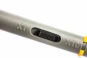
Switchable X1 X10 probes
For many years it was possible to obtain scope probes that could be switched between X1 and X10 operation. In fact many laboratories would use these almost exclusively.
However the large manufacturers have stopped manufacturing these switched versions and they are far more difficult to obtain these days.
The reasons given were that they were the source of many errors, as it was all too easy to leave the switch in the wrong position.
Another reason was that it compromised the performance oft he probes. With scope measurements now being made into the region of 100MHz and more, this is a really major factor.
The performance of the scope probe can considerably limit the performance of the overall scope measurements, and therefore no compromise on the probe performance can be accepted.
X10 oscilloscope probe compensation
The X10 scope probe is effectively an attenuator and this enables it to load the circuit under test far less. It does this by decreasing he resistive and capacitive loading on the circuit. It also has a much higher bandwidth than a traditional X1 scope probe.
The x10 scope probe achieve a better high frequency response than a normal X1 probe for a variety of reasons. It does this by decreasing the resistive and capacitive loading on the The X10 probe can often be adjusted, or compensated, to improve the frequency response.
For many scope probes there is a single adjustment to provide the probe compensation, although there can be two on some probes, one for the LF compensation and the other for the HF compensation.
Probes that have only one adjustment, it is the LF compensation that is adjusted, sometimes the HF compensation may be adjusted in the factory.
To achieve the correct compensation the probe is connected to a square wave generator in the scope and the compensation trimmer is adjusted for the required response - a square wave.

As can be seen, the adjustment is quite obvious and it is quick and easy to undertake. It should be done each time the probe is moved from one input to another, or one scope to another. It does not hurt to check it from time to time, even if it remains on the same input. As in most laboratories, things get borrowed and a different probe may be returned, etc . .
A note of caution: many oscilloscope probes include a X1/X10 switch. This is convenient, but it must be understood that the resistive and capacitive load on the circuit increase significantly in the X1 position. It should also be remembered that the compensation capacitor has no effect when used in this position.
As an example of the type of loading levels presented, a typical scope probe may present a load resistance of 10MΩ along with a load capacitance of 15pF to the circuit in the X10 position. For the X1 position the probe may have a capacitance of possibly 50pF plus the scope input capacitance. This may end up being of the order of 70 to 80pF.
Other types of probe
Apart from the standard 1X and 10X voltage probes a number of other types of scope probe are available.
- Current probes: It is sometimes necessary to measure current waveforms on an oscilloscope. This can be achieved using a current probe. This has a probe that clips around the wire and enables the current to be sensed. Sometimes using the maths functions on a scope along with a voltage measurement on another channel it is possible to measure power, as well as looking at the phase differences.
Read more about . . . . Oscilloscope Current Probes.
- Active probes: As frequencies rise, the standard passive probes become less effective. The effect of the capacitance rises and the bandwidth is limited. To overcome these difficulties active probes can be used. They have an amplifier right at the tip of the probe enabling measurements with very low levels of capacitance to be made. Frequencies of several GHz are achievable using active scope probes.
- Differential scope probes: In some instances it may be necessary to measure differential signals. Low level audio, disk drive signals and many more instances use differential signals and these need to be measured as such. One way of achieving this is to probe both lines of the differential signal using one probe each line as if there were two single ended signals, and then using the oscilloscope to add then differentially (i.e. subtract one from the other) to provide the difference.
Using two scope probes in this way can give rise to a number of problems. The main one is that single ended measurements of this nature do not give the required rejection of any common mode signals (i.e. Common Mode Rejection Ratio, CMMR) and additional noise is likely to be present. There may be a different cable length on each probe that may lead to a time differences and a slight skewing between the signals.
To overcome this a differential probe may be used. This uses a differential amplifier at the probing point to provide the required differential signal that is then passed along the scope probe lead to the oscilloscope itself. This approach provides a far higher level of performance. - High voltage probes: Most standard oscilloscope voltage probes like the X1 or X10 are only specified for operation up to voltages of a few hundred volts at most. For operation higher than this a proper high voltage probe with specially insulated probe is required. It also will step down the voltage for the input to the scope so that the test instrument is not damaged by the high voltage. Often voltage probes may be X50 or X100.
To help your home lab or workshop . . . . . .
To help you with your home workshop or radio shack, etc, we thought these might help:

P6100 BNC Oscilloscope Probe Kit 100MHz 1X 10X
Features a 1:10 attenuation ratio, 100MHz bandwidth, rise time of less than 3.5ns, at just 80g, the lightweight design ensures easy handling and transportation.

P6500B 500MHz Oscilloscope Probe 10X
P6500B probe is a 500MHz oscilloscope probe with a switch for 10x attenuation. This probe has an adjustment tool for adjusting the compensation capacitance to match the oscilloscopes.

OWON OW3200/OW3100/OW3070/OW3300 Digital Oscilloscope Probes 200Mhz 100Mhz 70Mhz Bandwidth
High Bandwidth Options:Choose from 200Mhz, 100Mhz, or 70Mhz bandwidths to capture intricate waveforms with precision.
Check out more items you might like from my Oscilloscopes store.
More convenient to buy from Amazon.com? Check out Oscilloscopes on my Amazon Storefront.
Note: We make a small commission from any sales at no cost to you.
Oscilloscope probes are an essential addition to any oscilloscope. The performance of the probe is crucial to that of the overall scope performance and therefore its performance should be selected to match that of the scope and the measurements envisaged.
In addition to its basic performance, each probe should have its compensation adjusted before use, otherwise the measurements could be wildly inaccurate.
 Written by Ian Poole .
Experienced electronics engineer and author.
More Test Topics:
Data network analyzer
Digital Multimeter
Frequency counter
Oscilloscope
Signal generators
Spectrum analyzer
LCR meter
Dip meter, GDO
Logic analyzer
RF power meter
RF signal generator
Logic probe
PAT testing & testers
Time domain reflectometer
Vector network analyzer
PXI
GPIB
Boundary scan / JTAG
Data acquisition
Return to Test menu . . .


