
Amplifier Classes: A, B, AB, C, D, etc
The way in which an amplifier operates is defined by its class - amplifier classes including A, B, AB, C, D and others are widely used.
Amplifier Design Concepts Includes:
Basic concepts
Amplifier classes
Amplifiers are given a classification according to the way in which they are biassed and they operate.
Amplifier classes including Class A, Class B, Class AB, Class C and the like are widely seen when dealing with amplifier specifications and their design.
The class of an amplifier is selected to meet the overall requirements. Different amplifier classes provide different characteristics, enabling the amplifier to perform in a particular way and also with a level of efficiency.
Amplifier classes overview
The different amplifier classes provide different performance characteristics. These make the different types of amplifier class suitable for different situations. A tabular summary of their different characteristics is given below.
| Amplifier Class Designations & Performance Summary |
||
|---|---|---|
| Amplifier Class | Description | Conduction Angle θ |
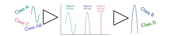
| Class A | Conduction over the full 360° of the cycle | θ = 2π |
| Class B | Conduction occurs over half the cycle, i.e. for 180° | θ = π |
| Class AB | Conduction occurs for slightly more than half the cycle, i.e. between 180° & 360° | θ < π < 2π |
| Class C | Conduction occurs for less than 180° of the cycle, but this creates distortion | θ < π |
| Classes D to T | These amplifier classes utilise non-linear switching techniques to improve efficiency. | N/A |
Class A amplifiers
A class A amplifier is biassed so that it conducts over the whole of the cycle of the waveform. It conducts all of the time, even for very small signals, or when no signal is present.
The Class A amplifier is inherently the most linear form of amplifier, and it is typically biassed to ensure that the output from the device itself, before it is passed through a coupling capacitor or transformer, sits at half the rail voltage, enabling voltage excursions equally either side of this central point. This means that the largest signal can be accommodated before it hits either the top or bottom voltage rail.
Normally a class A amplifier will start to become non-linear as the signal approaches either voltage rail, so operation is normally kept away from this situation.
For the amplifier to operate correctly in its class A condition, the no signal current in the output stage must be equal to or greater than the maximum load current for the peak of any signal.
As the output device is always conducting this current represents a loss of power in the amplifier. In fact the maximum theoretical efficiency that a class A amp can achieve is 50% efficiency with inductive output coupling or just 25% with capacitive coupling. In practice the actual figures obtained are much less than this for a variety of reasons including circuit losses and the fact that waveforms do not normally remain at their maximum values, where the maximum efficiency levels are achieved.
Accordingly, the Class A amplifier provides a linear output with the lowest distortion, but it also has the lowest efficiency level.
Class B amplifiers
A class B amplifier is biassed so that it conducts over half the waveform. By using two amplifiers, each conducting our half the waveform, the complete signal can be covered.
To achieve this, two active devices are used and input waveform is split so that one active device conducts during half of an input cycle, the other during the other half. The two halves are summed at the amplifier output to reconstruct the complete waveform.
At times, class B amplifiers called “push-pull,” because the outputs of the active devices have a 180° phase relationship. However this term is used less widely these days - it tended to be very common when vacuum tubes / thermionic valves were used and in recent years the term has fallen into disuse.
The efficiency is much higher, but the class B amplifier suffers from what is termed cross-over distortion, where one half of the amplifier turns off and the other comes into play. This results from non-non-linearities which occur close to the changeover point where one device is turning on and the other is turning off. This point is notoriously non-linear, and the distortion is particularly noticeable for low level signals where the non-linear section of the curve represents a much larger portion of the overall signal.
Although the maximum theoretical efficiency of a class B amplifier is 78.5%, typical efficiency levels are much lower.
Class AB amplifiers
As might be expected a Class AB amplifier falls between Class A and Class B. It seeks to overcome the cross-over distortion by slightly turning on the transistors so that they conduct for slightly more than half the cycle and the two devices overlap by a small amount during the switch-on / switch-off phase, thereby overcoming the crossover distortion.
This approach means that the amplifier sacrifices a certain amount of potential efficiency for better linearity - there is a much smoother transition at the crossover point of the output signal. In this way, Class AB amplifiers sacrifice some of the efficiency for lower distortion. Accordingly class AB is a much better option where a compromise between efficiency and linearity is needed.
Classes AB1 & AB2
Thermionic valves or vacuum tubes were widely used for high power audio and RF linear amplifiers. To save cost, weight and power consumption, amplifiers were run in class AB, and two amplifier sub-classes were often mentioned: Class AB1 and AB2. These sub-classes are applicable to only thermionic or vacuum tube technology as they refer to the way in which the grid was biassed:
- Class AB1: Class AB1 is where the grid is more negatively biased than it is in class A. In Class AB1, the valve is biassed so that no grid current flows. This class of amplifier also gives lower distortion than one running in class AB2.
- Class AB2: Class AB2 is where the grid is often more negatively biased than in AB1, also the size of the input signal is often larger. In this class grid current flows during part of the positive input half-cycle. It is normal practice for the Class AB2 grid bias point to be closer to cut-off than occurs in Class AB1, and Class AB2 gives a greater power output.
Class C amplifiers
A Class C amplifier is biassed so that it conducts over much less than half a cycle. This gives rise to very high levels of distortion, but also it enables very high efficiency levels to be achieved. This type of amplifier can be used for RF amplifiers that carry a signal with no amplitude modulation - it can be used for frequency modulation with no issues. The harmonics created by the amplifier effectively running in saturation can be removed by filters on the output. These amplifiers are not used for audio applications in view of the level of distortion.
Class C amplifiers typically use a single active device that is biased well into its off region. As the signal is applied, the top peaks of the signal cause the device to run into conduction, but obviously for only a small portion of each input-waveform cycle.
At the output the circuit uses a high-Q, L-C resonant circuit. This circuit effective rings after it is hit by each pulse so that the output contains an approximation to a sine wave. Filtering is required on the output to ensure that the level of harmonic is sufficiently low.
Typically, the conduction angle for the transistor is significantly less than 180° - often around the 90° region. Efficiency levels can be as high as 80%, but values of 66% are more normal when circuit losses, etc are taken into account.
Amplifier Classes D to T
There is a variety of different amplifier classes which tend to be based upon switching techniques rather than using analogue approaches.
- Class D Amplifier: A Class D audio amplifier utilises switching technology within the amplifier. As the output devices are either on or off, Class-D amplifiers can theoretically reach efficiency levels of 100%. In reality the actual levels attained are less, but nevertheless the efficiency levels achieved are very much higher than the other analogue classes.
One of the first class D amplifiers for audio use was introduced by Sinclair in the UK around 1964. Although the concept was good in theory, the amplifier did not work particularly well, and when it did, the amplifier tended to cause large amounts of interference to local radio and television sets as EMC precautions were not normally applied to equipment at this time. Class G Amplifier: Class G is a form of amplifier that uses multiple power supplies rather than just a single supply. For low level signals a low voltage supply is used, but as the signal level increases, so a high voltage supply is utilised.
This is gradually brought in to action up to full rated power output as required. This gives a very efficient design as additional power is only used when it is actually required.
The change to the higher voltage supply can be achieved without detriment to the output signal fidelity. In this way, the amplifier is able to provide both low levels of distortion, whilst also providing high levels of efficiency.
This approach can be complex to design from scratch, but if engineered correctly, it can work well. Fortunately the difficulty of design can be reduced if one of the many audio ICs that use Class G is used.
Summary of common amplifier classes
Here I give my quick summary of the salient points about the different more commonly used amplifier classes.
Class A: This is the least efficient (maximum of 50%) but offers the best linearity. It is often used for low level amplifiers and where the best linearity is required.
Class B: This class offers better maximum efficiency levels (theoretical maximum of 78.5%) and it is generally used for push-pull amplifiers where each half of the amplifier works on half the cycle. These amplifiers are sometimes used for audio work, but care needs to be taken in managing the crossover point where one side of the amplifier changes to the other. What’s known as crossover distortion can occur.
Class C: This is the least linear but offers best efficiency. It is often used for RF amplifiers where the harmonics resulting from the non-linearity can be filtered and where no amplitude elements of modulation are on the signal. It’s great for FM transmitters and those carrying phase modulation.
Class D: This is a switching form of amplifier which can be used to considerably increase the level of power consumption.

There are very many more amplifier operational classes available to the designer these days. Modern silicon technology has opened up many more doors, but despite this, the basic three amplifier classes of class, Class B, and Class C, with the derivative Class AB which is a cross between Class A and B are still the most widely used.
 Written by Ian Poole .
Experienced electronics engineer and author.
More Circuits & Circuit Design:
Op Amp basics
Op Amp circuits
Power supply circuits
Transistor design
Transistor Darlington
Transistor circuits
FET circuits
Circuit symbols
Return to Circuit Design menu . . .


