Amplifier Design Basics
Amplifiers are one of the main building blocks within electronic circuits, especially analogue circuits, where they provide an increase in the signal level.
Amplifier Design Concepts Includes:
Basic concepts
Amplifier classes
An amplifier is a term that is used to describe a circuit that increases the level of the signal that enters it.
Amplifiers are used in a variety of areas from audio applications through to radio frequency ones.
However for all amplifiers whether DC, audio, radio frequency, small signal, large signal, or for any other application, there are many common considerations.
Electronic amplifiers can be classified in many ways. They can offer high input impedances, low output impedances, they can have a variety of different bias and operational modes. High power, low noise, class A, class B, class C and so forth. Each type is chosen to suit a different application.
Amplifier circuit symbol
The normal amplifier symbol is a triangle and within overall block diagrams, this is often included within a square as shown below.

Often the amplifier symbol, especially when used within a circuit itself is depicted just as a triangle as below.

This second symbol is the one that is typically used to denote an operational amplifier, or op amp within a circuit.
Amplifier design basics
An amplifier can be made in many ways. They can use bipolar transistors, field effect transistors and even thermionic valves / vacuum tubes. The amplifiers can be included within some form of circuit block or integrated circuit. They can even be in the form of operational amplifiers, op amps.
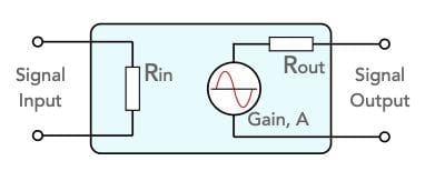
An amplifier can be considered as a block that has two input terminals and two output terminals. As the ground connection is normally common to input and output there are often only three terminals: input, output and the common.

Note: Although the "cold" ends of the input and output are normally grounded, they have been shown separately here as this is a generic diagram
An amplifier has three main properties:
Input resistance - Rin: The input resistance is the resistance that is seen by a signal source when it is applied to the input of the amplifier. The input resistance will become a load to the source. The case where the load is purely resistive is a special case, and more normally it will be an impedance. However for the purposes of this explanation it will be considered to be resistive.
The input resistance can be easily determined by measuring the input current and voltage, and using Ohm's law to determine the resistance.
Output resistance - Rout The output resistance is the resistance that can be considered to be within the amplifier as shown below. It will form a potential divider network with any load that is applied to the amplifier. Again the output will have indicative ad capacitive elements which mean it will be an impedance, but for most low frequency applications and for this explanation, it can be considered to be resistive.
The output resistance can be determined by measuring the output voltage under a no load condition, and then a loaded condition, i.e. with the applied load. Knowing the open circuit voltage and the load resistance and the voltage dropped across the internal resistance under load it is possible to determine the source output resistance.
Gain: The gain of the amplifier is obviously a key element of its performance.

Voltage gain of an amplifier Normally the voltage gain, AVis the key factor of interest. This is defined as the output voltage divided by the input voltage:
Often within an amplifier the waveform may be inverted, and this is represented by the fact that the gain is negative. In other words if the amplifier had an absolute value of gain of 5, but it inverted the signal, for a 1 volt input, the output would be - 5 volts, and when entered into the equation, this would give a gain of -5.

Amplifier output voltage inverted, i.e. 180° out of phase with input It is also possible to have current gain within a circuit. This is particularly useful when needing to drive a low impedance load. It is necessary for the current level to be increased, often keeping the voltage the same. Circuits like bipolar transistor emitter followers, FET source followers, op amp buffers with 100% feedback, and for this using tubes / valves the circuits used for this are typically cathode followers.
When using a circuit to provide current gain, it is often necessary to ensure that the circuit has sufficient drive capability. Whist the circuit may be able to provide the level of current gain for low levels of current, in some cases they may not be able to provide high levels of current that may be required in some instances. Using a very obvious example, a small op amp buffer would not be able to drive a large loudspeaker on its own.
Amplifier power gain and design
It is sometimes useful to define the power gain provided by an amplifier when testing or designing one. This is often of great interest for RF amplifiers, especially those used in transmitters.
As power is the voltage multiplied by the current in a circuit, the power gain can simply be expressed as the product of the two.
When specifying the power gain of an amplifier, it is normal to express it in decibels:
It is also possible to use the voltage and current levels to provide gain expressed in dB, but any changes in impedance must be accounted for.
Note on the decibel:
 The decibel, a tenth of a Bel, is a logarithmic way of comparing two power levels. As many quantities in electronics vary by huge amounts, this logarithmic format is very useful.
Read more about the decibel.
Amplifier efficiency
One of the key design parameters for any amplifier is its efficiency. This can be particularly important for battery power equipment where battery life is of importance.
The efficiency of the amplifier is essentially the output power divided by the input power. Normally the input power is taken to be the DC power applied to supply the amplifier.
The efficiency is also expressed as a percentage. In this way the basic efficiency of the amplifier looking only at the DC input can be taken as follows:
The efficiency level of an amplifier will depend upon a host of factors including the class of the amplifier, how close to the rails the output signal extends, losses within the circuit, etc..
Amplifier classes
Reference to amplifier classes including Class A, Class B, Class C, Class AB and others will often be seen when investigating the form of amplifier. When designing an amplifier, the class is often one item that will appear early in the design cycle.
By changing the way an amplifier is biassed, it is possible to change the way it works and improve the efficiency level, but often at the cost of the amount of distortion created.
Some of the main amplifier classes are listed below:
- Class A: For a class A amplifier, it is biassed so that it conducts over the whole of the cycle of the waveform. It provides a linear output with the lowest distortion, but it also has the lowest efficiency level. The maximum theoretical efficiency is 50% but this level is seldom reached and efficiency levels of 20% or less are not unexpected.
- Class B: A class B amplifier is biassed so that it conducts over half the waveform. By using two amplifiers, each conducting our half the waveform, the complete signal can be covered. The efficiency is much higher, but the class B amplifier suffers from what is termed cross-over distortion, where one half of the amplifier turns off and the other comes into play. This results from non-non-linearities which occur close to the turn-off point. Although the maximum theoretical efficiency of a class B amplifier is 78.5%, typical efficiency levels are much lower.
- Class AB: As might be expected a Class AB amplifier falls betweenClass A and Class B. It seeks to overcome the cross-over distortion by slightly turning on the transistors in their quiescent state, so that they conduct for slightly more than half the cycle, thereby overcoming the crossover distortion.
- Class C: A Class C amplifier is biassed so that it conducts over much less than half a cycle. This gives rise to very high levels of distortion, but also it enables very high efficiency levels to be achieved. This type of amplifier can be used for RF amplifiers that carry a signal with no amplitude modulation - it can be used for frequency modulation with no issues. The harmonics created by the amplifier effectively running in saturation can be removed by filters on the output. These amplifiers are not used for audio applications in view of the level of distortion.
There are other amplifier classes, but these adopt some slightly different techniques.
Amplifiers are one of the most widely used circuits - they are used for audio, DC, radio frequency and very many other applications. They are one of the most common analogue circuits. There is a huge variety of circuits, whether used with op amps, bipolar transistors, FETs of even the old vacuum tubes / thermionic valves.
Whatever the devices used in the circuit, the basic principles are the same, and can be applied whatever form of device is used.
 Written by Ian Poole .
Experienced electronics engineer and author.
More Circuits & Circuit Design:
Op Amp basics
Op Amp circuits
Power supply circuits
Transistor design
Transistor Darlington
Transistor circuits
FET circuits
Circuit symbols
Return to Circuit Design menu . . .