What is a Radio Access Network, RAN for Mobile Communications
The Radio Access Network or RAN is one of the key elements of any mobile communications network enabling connectivity to the user via a radio link
Cellular / Mobile Telecommunications Basics Includes:
What is cellular communications
Concept of cellular system
Radio access network, RAN
Basestation Technology
Base station antenna technology
Multiple access techniques
Duplex techniques
What's inside a cellphone
SIM cards
Handover
Backhaul
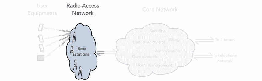
The Radio Access Network or RAN is the part of the mobile communications or cellular telecommunications network that interfaces with the user equipment, mobile phone, tablet or whatever.
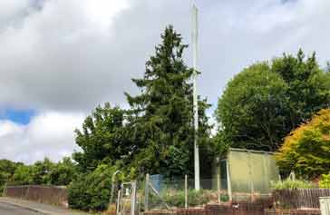
In many ways it is one of the more visible elements of the mobile network because the antennas, and associated equipment can be seen all around the country, in towns and many other areas.
Although the towers and the associated are the main visible element fo the radio access network, there is a considerable amount of electronics associated with the tower and associated units are normally seen at ground level to accommodate all the required electronics.
Radio Access Network, RAN definition
The radio access network is such a key element of any mobile communications network. As it interfaces to other elements, it is useful to know what it includes and what it does not.
As a result, it is worth having a short definition of what a radio access network is so that a quick understanding of what it is can be gained.
Radio Access Network, RAN definition:
The radio access network or RAN within a mobile communications network is the portion of the network that is used to connect individual user devices such as mobile phones, or cellular enabled tablets, laptops or other devices to other parts of a network using a radio connection.
This definition is rather broad and as the technology required to support mobile communications has changed, so too has the way in which the radio access network is implemented has changed.
It has been developed to become more responsive and yet more flexible so that it can handle a large number of users more effectively.
The RAN itself consists of a network of the base stations or mobile phone towers, poles, antennas, etc placed strategically over towns and countryside to give the required coverage within a patchwork of cells.
As many thousands of these base stations are deployed, they need to be as effective as possible, located to give the required coverage and capacity, etc.
The technology for the radio access network is continually evolving, and although the basic concepts and requirements remain the same, the way the radio access network is implemented has changed to enable more efficient and effective use of the resources available.
Concept of cells in a radio access network
A cellular telecommunications network is based around the concept of using a large number of small cells, each served by a different base station.
By adopting this approach it is possible to re-use channels or frequencies many times over to enable the vast number of mobile phones that are used today to main connected to the network virtually all the time.
The idealised concept for a cellular network shows a number of perfectly adjoining cells, each of the same size

In reality, the cell sizes vary and they are not hexagonal, and some overlap with others and there are sometimes areas which are not properly illuminated with the signal giving a coverage hole.
The aim of planning a network is to fully cover the required area, and also have sufficient capacity to handle the number of mobiles that are likely to be connected and the data they may consume.
This is key to the successful operation of the radio access network, but it is also important to have the required hardware.
Radio Access Network hardware
The purpose of the radio access network is to connect to the user mobile devices and then link them back into the core network.
The mobile phone basestation is the visible implementation of the radio access network. The most iconic of these are the mobile phone towers that are seen in all countries these days.
However the mobile phone basestations can take many forms: they can be based around a tower with its antennas; they may be located on the top or side of tall buildings in a locality; small ones may even be located on lampposts of other suitable existing poles, etc; and some may even be located behind shopfronts, etc.
Whatever the type of basestation, they are all built up from similar building blocks, according tot he requirements of the particular situation.
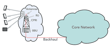
The RAN hardware comprises a network of base stations that have three main elements:
Antennas: The antennas are probably the most visible part of the RAN, being placed at the top of the tower or in another visible position. These antennas radiate the transmitted signal from the base station and receive signals from the mobiles in its coverage area. The antennas typically have a controlled radiation pattern to ensure they only radiate and receive in a specific direction to minimise interference to and from other cells.
Read more about . . . . Base Station Antennas.
Radio Unit: The radio unit can be referred to by a number of different names according to how it is used. It can be the radio unit, RU, or radio head, and if it is remote, it can be called the remote radio unit, RRU, or remote radio head, RRH.
This element of the RAN contains the transmitter and receiver. Both the transmitter and receiver need to be able to handle the form of modulation and the waveforms for the particular mobile phone generation.
Baseband Unit, BBU: The base band unit is effectively the controller for the base station. It organises the links to the various mobiles, organises the data and controls the Radio Unit, and provides a large number of other functions including processing, detecting errors, securing the wireless signal and ensuring that the wireless resources are used effectively.
Of course, it is necessary to remember that the whole radio access network consists of many thousands of base stations suitably located to give the required coverage for their individual cells.
Radio Access Technology, RAT
The radio or wireless communication technology that provides the link between the basestation antenna and the mobile has evolved significantly over the years.
What is termed the radio access technology or RAT, has evolved from 2G GS, through advances including GPRS and EDGE to 3G UMTS with its HSPA enhancements to 4G LTE, 5G and with 6G on the horizon.
In order for the basestation and the mobile to be able to communicate, they must be able to use a common radio access technology. These days, most base stations and mobile phones are able to use a variety of different RATs.
That said, 2G and 3G are now being withdrawn in many networks and countries to free up spectrum for the more advanced and spectrum efficient later technologies of 4G, 5G, etc.
Additional elements.
The radio access network needs to be able to communicate wit the core network to be able to send the data being sent and received by the user equipments. It also needs to communicate over issues including handover, authentication and many other aspects of the operation of the network.
This data is sent over a link which could use any one of a number of techniques including, fibre, microwave, and in the early days of mobile phones, even wired E1 or other links were used. This link is normally referred to as the "backhaul" link.
The cellular network is made up from a patchwork of areas called cells. A cell is served by at least one radio transceiver, and typically this is three or four as it can be seen that each mast contains three or four antennas in most instances. Smaller 'poles" will not contain this number and will typically have a smaller coverage area.
Evolution of the radio access network
Radio access networks have evolved significantly since the first generation analogue networks were deployed. The experience from deploying networks, the advances in technology and the enormous increase in demand for mobile communications has lead to some significant changes and a variety of approaches have been used.
Over the years, the radio access network has needed to evolve to meet the ever increasing requirements placed upon the overall mobile communications system and in particular the network.
The need for providing higher levels of performance and reducing the cost has enabled todays mobile networks to offer very high levels of performance for a cost that is affordable by most.
To look at how the technology has evolved, the second generation and third generation RAN architecture, used a RAN controller to manage the nodes connected to it. The RAN's network controller managed aspects including the radio resources, mobility and data encryption. This connected to the circuit-switched core network and later a packet-switched core network.
When 4G was being devised it was realised that packet data would be the way data would be carried and as a result an all IP network was used.
This resulted in changes to the RAN architecture with the introduction of techniques such as the introduction of C-RAN which split the radios and antennas from the baseband controller to adapt better to the modern demands of mobile devices. See below for more details.
The next evolution of the radio access network occurred for 5G. For this the RAN architecture was divided so that the user plane and the control plane were split into separate elements.
For this the BBU was broken into two units called the distribution unit or DU and the central unit or CU.
The DU provides the functionality to operate the radio link and the medium access control layers in addition to some of the physical layer operation.
By contrast the CU controls the radio resource control protocol, which controls many aspects of the operation including the including information broadcasts, establishing and closing connections between the user equipment and the RAN, and it also controls the quality of service. It also provides management of the packet data including compression and decompression of the IP data stream headers as well as transferring the user data between other functions.
One of the advantages of splitting the CU and DU is that the CU can be physically located at either the base station itself, or it can be located at a more central or convenient site where several CUs can be combined providing cost savings and performance improvements.
Types of radio access network, RAN
The changes have given rise to a number of types of RAN and there are various different names that have been applied over the years.
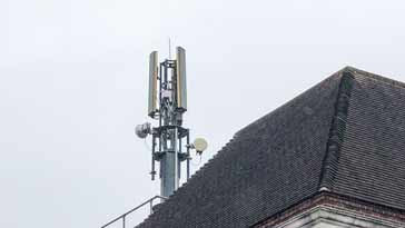
Note the microwave parabolic reflector antennas for backhaul
When looking at various written material, reference will be seen to a variety of different types of RAN, and it is worth taking a quick look at them to understand the differences.
GRAN: GRAN stands for GSM RAN, and it was the basic radio access network architecture that was used for the 2G GSM networks.
GERAN: GERAN stands for GSM EDGE Radio Access Network. As GSM evolved to incorporate EDGE and its data capability, the radio access network needed to accommodate additional capabilities to handle the levels of data now being carried.
UTRAN: UTRAN was the form of radio access network used with 3G UMTS - the abbreviation stood for UMTS RAN.
E-UTRAN: The E-UTRAN was developed alongside 4G LTE and the abbreviation stood for Evolved UTRAN.
C-RAN: This abbreviation is used to denote cloud RAN or it is sometimes called centralised RAN. For C-RAN, the elements of the traditional RAN are separated and the remote radio heads are located as normal, but the base band processing units are centralise so that the resource can be shared and more effective control of the RRHs can be achieved, especially when users are handing over from one cell to the next.
O-RAN: One of the major issues with RAN technology is that it consists of many different elements. There are the radio heads containing the RF transmitter and receiver and the base band units containing the control and processing. Traditionally there has been no standardisation of the links between the two main units, as well as other elements within the overall RAN.
Therefore it is only possible to link RRHs to a limited number of types of BBU, for example. By having an open standard it is possible to optimise the system for its particular location and situation by selecting the best RRH and BBU for example, and not limited to units from a given manufacturer. In other words O-RAN has an open standard for the elements within the base station.
The radio access network acts as the main interface between the user equipment, whether it is a mobile phone, cellular enabled laptop, tablet etc or a remote device and the core network. It provides the radio link between the two as well as many other functions.
The radio access network is typified by the base stations we see around towns and the countryside, but inside these visible manifestations there is a considerable amount of functionality and the technology is developing all the time.
 Written by Ian Poole .
Experienced electronics engineer and author.
Wireless & Wired Connectivity Topics:
Mobile Communications basics
2G GSM
3G UMTS
4G LTE
5G
Wi-Fi
Bluetooth
IEEE 802.15.4
DECT cordless phones
Networking fundamentals
What is the Cloud
Ethernet
Serial data
USB
LoRa
VoIP
SDN
NFV
SD-WAN
Return to Wireless & Wired Connectivity