
Base Station Antenna Technology for Mobile Networks
The technology associated with cellular base station antennas is becoming ever more complicated as the mobile systems migrate from one generation to the next and the demands placed on antennas increase.
Cellular / Mobile Telecommunications Basics Includes:
What is cellular communications
Concept of cellular system
Radio access network, RAN
Basestation Technology
Base station antenna technology
Multiple access techniques
Duplex techniques
What's inside a cellphone
SIM cards
Handover
Backhaul
The base station antenna is the item of the overall mobile communications network that is the closest to the user. It radiates and receives the signals to and from the user.
The base station antennas, BSAs, are visible in towns and cities as well as in rural areas and in fact in any area where mobile phone of cellular communications coverage is required.
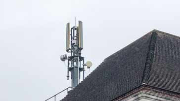
The techniques used within these antennas is moving forward all the time and the technology used is advancing in line with the requirements for the radio access networks and the transitions from one mobile communications generation to the next.
Although there may appear to be comparatively little difference when these antennas are viewed from the ground, especially if the whole antenna is encased in a weather protective shield, there is a considerable amount that has changed over the years.
To better understand the technologies used within current base station antennas, it is probably easiest to understand the current antenna options by seeing how the antenna technology developed alongside the mobile communications requirements.
In this way, the technology can be better understood along with the reasons for introducing the various techniques and technologies.
Basic antenna technology
Most base station antennas use a collinear form of antenna consisting of a number of dipoles mounted vertically above each other.
If the dipoles are driven in phase then the wavefronts from the individual dipoles reinforce each other at 90° to the axis of the dipoles.
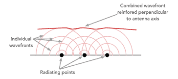
This directs the power in the direction in which it is wanted, and reduces the power in directions where it is not wanted. This means that the most effective use is made of the power available, and also in terms of the receiver, the gain can be used to ensure the weaker signals from the mobiles are received satisfactorily.
Often the arrays are tilted down slightly to ensure that the signal does not "spill" over into nearby cells that may be using the same channels as this would give rise to increased levels of interference, etc.
Typically vertically stacked dipole or looped dipole elements are used within the antennas, providing a good form of radiating source.
The antennas are typically fabricated on circuit boards as this means that they are not only mechanically rigid, but the dimensions can be controlled very accurately and this is a particularly important factor at the frequencies being used - even a few millimetres can make a significant difference.
Early antenna systems
The base stations for the first generation mobile networks used omnidirectional antennas because the initial loading on the individual cells was relatively low.
The main aim at this stage was to provide the best coverage. These antennas were mounted on the top of the towers to provide general omnidirectional coverage, and a single antenna was used, and not the multiple antennas seen today.
Interference between cells was not too much of an issue because the distances between cells was relatively large at this time and because of the "capture effect" of frequency modulation -f the form of modulation used, the interference was not as noticeable.
Sectorisation
With the introduction of the digital second generation systems the costs fell and the usage of mobile communications systems increased very rapidly.
To increase the capacity of the system, one easy method was to split each cell into three sectors. These would have tree antennas, each with a beamwidth of 120°. Typically the beamwidth was measured at the -10dB point.
By having three antennas on the tower, there could be considerable savings on the cost of towers, the base station hardware, backhaul links, and also in the time delays for local planning that was needed in many countries.
Initially only three sectors were used, but as time passed, the needs grew to increase capacity further and as a result sectors were made smaller by narrowing the beamwidth and adding additional antennas. Half power beamwidth figures of 65° and even 33° were used.
However this meant adding an increasing number of antennas to a tower and this considerably increased the loading as well as the visual impact.
Spatial diversity
As a result of multi-path effects, it is possible that reception on one antenna could be subject to multi-path fading, whereas another antenna placed only a short distance away cold receive the signal perfectly well.
One example of how spatial diversity was used in some early base station antenna systems can be seen where two vertical antenna poles are seen on a mast. One of the antennas was used for transmission and both were used for reception. The two antennas were used for reception to provide diversity reception.
As multi-path effects could often mean that reception was poor on one antenna, the second antenna gave another option because it was possible that reception on this antenna would one much better because of the spatial difference.
The same principle was also used on some later towers where sectorisation was employed and two antennas were sued for each sector for the same reason.
Polarisation
Another method or providing diversity is to distinguish between two orthogonal modes of polarisation.
Typically the polarisation used for the basic antennas was vertical. Not only were the antennas placed above each other on the same axis, but the polarisation of the antennas and their radiation was in the vertical axis.
This made sense because the early car and transportable phones had vertical antennas, and the truly mobile or hand carried sets later had antennas that tended to be relatively vertical.

However to improve performance, another technique to provide diversity was to use two cross polarised antennas. Using this technique, not only was the polarisation slanted, but the antenna consisted of two vertical series of antennas polarised in different directions, one at an angle of +45° to the vertical and the other at -45° to the vertical.
As the polarisation was different for the two antennas, this provided another means of providing diversity.
Polarisation diversity is now the dominant base station antenna form of providing diversity.
Antenna tilting
It is often necessary to tilt the antennas downwards slightly so that the radiation covers the ground within the coverage area and does not spill over too much into neighbouring cells.
It is found that mechanically tilting the antenna will distort the footprint, whereas electrically tilting the beam by changing the incremental phase difference between the individual radiating elements within the overall antenna is far more efficient and effective.
Initially a scheme known as mechanically adjustable electrically tilted antennas was used whereby the relative phase between the elements was changed using phase shifters in the feed network.
Later remote electrical tilt, RET, was introduced, and this enabled the tilting to be adjusted remotely at the network control centre.
Remotely titling the antenna allowed for the cell footprint to be dynamically adjusted, not only to improve the general coverage to what was required, but also to provide optimum coverage during changing scenarios such as rush hours and the like.

To achieve this, the phase between the different antenna elements within the overall antenna can be shifted, one relative to the next.
This is achieved by using a programmable phase shifter with the antenna. By changing the relative phase between one element and the next, it is possible to tilt the antenna beam pattern as required.
Typically only small shifts are needed and as they are electrically controllable, they can be undertaken remotely as the overall network performance is monitored.
Multiband antennas
Soon after the 2G networks were introduced, more spectrum was needed to provide the required capacity. As more bands were released, individual operators found themselves with spectrum allocations at different frequencies.
With sectorisation adding additional antennas to towers and loading and visual impact being issues, the concept of a dual band or multiband antenna became very attractive.
As the individual radiating elements within an antenna have a limited bandwidth, it was necessary to have separate sets of radiating elements for each band.. These were typically aced side by side with each other to enable two antennas, one for each band to effectively be contained within the overall antenna construction.

When deploying dual band antennas it is necessary to consider the characteristics of the two antennas within the overall antenna construction.
It is found that at higher frequencies the radio signals are more easily absorbed at higher frequencies by objects like houses, trees and other items, but there is also a need to provide the same coverage on both bands. Also for higher frequencies, it is possible to provide a higher level of gain for the same physical antenna length because the wavelength at higher frequencies is shorter.
Choices need to be made when planning the network about the antenna performance. Accordingly two options are provided for cell planners:
- Maximum gain antenna: For this option the full length of the array is used for both bands. This means that the higher frequency antenna will have more gain, and a narrower directive pattern.
- Equal gain antenna: For this approach, the gain of the antenna is limited to provide the same gain and approximately the same radiation pattern as the lower band.
The network planner can make choices about the coverage provided by both bands from the particular base station antenna system.
The amount of spectrum allocated to mobile communications has increased to accommodate both the number of users and the amount of data being handled. This has meant that many bands beyond the traditional regions around 900MHz and 1800 / 1900MHz have been used. Bands are allocated in the regions 650 - 900 MHz, 1695 - 2760 MHz and 3.2 - 3.6 GHz, dependent upon the country and region of the globe.
To accommodate all of these bands, many antennas cover three and four bands, etc.
Also as some of the higher frequency antennas are smaller, some antenna units may have two antenna sets for a given band.
Multibeam antennas
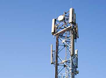
As can be seen on the buildings and towers around towns and the countryside, the antenna systems tend to have multiple antennas. Towers have a limited capacity for antennas, particularly if they are shared by multiple networks each requiring their own antennas.
As the needs for capacity have increased, so the need to have smaller sectors has grown and this could result in an increase in the number of antennas required.
One solution to this is to develop and introduce antennas that are able to produce more than one beam.
Using a twin beam base station antenna, it is possible to replace two single beam antenna with just one twin beam antenna.

This not only reduces the number of antenna required and reduces the visual impact and loading on the tower, but its also saves in cost as a single twin beam antenna is less costly than two single beam ones.
The twin beams or even multi-beams are achieved by introducing hybrid couplers into the feed network and feeding the antenna elements with the required phase signals.
Antennas for MIMO
As mobile communications systems developed, MIMO, or multiple input multiple output systems were introduced. This technology was first introduced for 4G LTE-A with 3GPP Rel10.
MIMO is a technology that utilises the multiple paths that a signal will travel to enable better signal to noise ratios to be achieved on the RF signal or to provide additional signal paths to increase the data rate, or a balance between the two.
Note on MIMO:
MIMO is a form of antenna technology that uses multiple antennas to enable signals travelling via different paths as a result of reflections, etc., to be separated and their capability used to improve the data throughput and / or the signal to noise ratio, thereby improving system performance.
Read more about MIMO technology
To make use of these different radio signal paths, multiple antennas must be used, either at the base station, the user equipment, or both.
As it is much easier to install multiple antennas at the base station, this is typically where the multiple antennas are found, although some user equipment possess them.
To achieve viable MIMO operation, the different antennas must be spaced at least 0.7λ apart.
When MIMO started to be deployed, some antennas already had two and sometimes even four high band arrays within the antennas. This arose because the high band antennas were very much smaller than the low band ones.
This meant that some base stations could be very easily upgraded to provide MIMO without the need to change the antenna.
In view of the space required, MIMO tends to be implemented more often with the high band arrays within a base station antenna although it has also been used with low band arrays as well.
Base station antenna technology is advancing all the time. Although the antennas may appear to remain the same and follow the same format because they look the same from the ground, nothing could be further from the truth as these antennas are evolving to become exceedingly complex high performance items that are an essential part of the overall mobile communications radio access network and of the whole mobile communications network as a whole.
 Written by Ian Poole .
Experienced electronics engineer and author.
Wireless & Wired Connectivity Topics:
Mobile Communications basics
2G GSM
3G UMTS
4G LTE
5G
Wi-Fi
Bluetooth
IEEE 802.15.4
DECT cordless phones
Networking fundamentals
What is the Cloud
Ethernet
Serial data
USB
LoRa
VoIP
SDN
NFV
SD-WAN
Return to Wireless & Wired Connectivity


