
Understand Cellphone Basestation Technology
Understand the major elements within a cellphone or cellular network base station, what each element does and how the technology is evolving to provide more flexible operation & better performance.
Cellular / Mobile Telecommunications Basics Includes:
What is cellular communications
Concept of cellular system
Radio access network, RAN
Basestation Technology
Base station antenna technology
Multiple access techniques
Duplex techniques
What's inside a cellphone
SIM cards
Handover
Backhaul
The base station is the most visible element of a mobile or cellular telecommunications network.
These cell phone base stations can take many formats, but they are characterised by the antennas on masts or tall buildings.
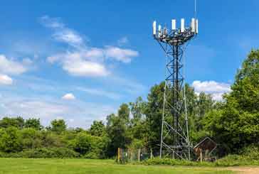
Even though the technology behind the antennas themselves is sophisticated, there is considerably more to a mobile phone base station than just the antennas and the tower.
The overall radio access network is built up from a host of cellular base stations, each of which cover their own coverage area which may consist of one of more cells.
Elements of a cellular base station
There are several distinct elements to a mobile phone base station. Each of these elements provides a separate function, and as the technology has advanced, some are separated out from the others, or they may be located in slightly different positions as the technology has advanced.
Although base stations can take many forms: some as traditional towers with antennas at the top, some with the antennas on the top of buildings, some as poles, and soem in a variety of other formats, they nevertheless all have the same basic format.
The main elements within the base station are the following entities:
Antenna system: The antenna system is the most obvious element of the base station and the antennas on towers and buildings tend to have a very distinctive shape.
Tower: In order to raise the antennas to a sufficient height to gain the coverage required, the traditional approach is to use a tower, although the base stations may be located in many other places including on top of buildings.
Radio Unit, RU / RRU: The radio unit is also often referred to the RRU- Remote Radio Unit, RFU - Radio Frequency Unit, or the RFH - Radio Frequency Head, but despite the different names they all refer to the same element. As the name indicates, it contains the radio frequency elements of the system.
Baseband unit: The baseband unit is that part of the caters for the signals that are at baseband. It is fundamentally a digital based entity that incorporates a variety of forms of processing.
Power system: The power system is needed to provide the variety of power requirements for the various entities within the mobile phone base station at all times, and under all conditions.
Backhaul: Although this is not strictly part of the cellular base station, it interfaces directly with it to provide the link with the main core network.
Development of cellular basestations from 2G onwards
As would be expected, there has been a considerable degree of development of base station technology and the formats used since the 2G implementations of the 1990s.
Not only has technology moved forward enabling many units to become more compact, but reliability has also improved, there has been a moved toward virtualisation in several areas, and the the functionality has also moved forward.
As a result of all the changes in technology, the topology has changed slightly as well, so the terms for various elements and where they are located needs to be kept rather fluid across the different generations.
For 2G GSM, the core network was connected to a Base Station Controller, BSC which might control just a few Base Station Transceivers, BTSs, i.e. masts in a locality.

For 3G UMTS, the nomenclature changed slightly so that the core network was connected to a Radio Node Controller, RNC which in turn was connected to a nodeB with the mast and antennas.
The traditional layout was still that the Radio Unit and the Baseband unit were located in a cabinet close to the base of the antenna mast or some other convenient position dependent upon the actual physical layout, e.g. where antennas are located non roofs, etc.
One of the key differences between 2G and 3G was that packet switching was introduced as opposed to the circuit switching that was predominant for 2G GSM.

For 4G, the two layers of the previous generations were reduced to one to provide a lower latency level and other performance enhancements. The new base station was referred to as a an eNodeB.
For 4G and ongoing to 5G, a more distributed architecture was used. Typically the RF unit was located much nearer the antenna to reduce losses and generally improve performance.
The baseband unit could be located in a cabinet at the base of the antenna tower, or increasingly it, or elements of it could be located remotely because fronthaul (the link between the BasebandUnit and the RF Unit) were improved.

For 5G further improvements were introduced to improve aspects including bandwidth and speed. In particular virtualisation was introduced far more as well as aspects like Open RAN.
However the overall topology of the base station functionality remained very much the same.
Detailed descriptions.
Although basic descriptions have been given for the different units or entities within a cellphone base station, more detailed information is given in the paragraphs below.
• Base station antennas
The cellular base station antennas have a distinctive shape and look, and they enable the There is a considerable amount of technology involved within them to enable them to provide very highly defined beams, some of which may be steerable, some may incorporate MIMO capabilities where they are able to utilise the multipath aspects of the signal to provide increased signal gain and / or increased bandwidth, others may offer diversity reception to overcome signal issues, etc..
The sizes of the antennas are governed by the wavelength of the signals being used as well as the beamwidths and capabilities, and this means that they have tended to remain about the same size, for those used on towers and tall buildings, etc. However some smaller antennas are used where the visual impact is an issue, or where the subscriber numbers are smaller resulting in a reduced capability for the antennas.
The antenna systems and their technology have developed considerably over the years and are now highly sophisticated systems in their own right.
• Base station towers & locations
These towers can be a variety of different heights according to the coverage required and the local planning regulations.
However in areas that are already built up, it is not possible to use a new tower, but instead the antennas and in fact the overall base station electronics are placed on top of suitably placed buildings.

Other base stations may be included in other areas, and they may even be located on existing utility poles, making them much less obvious.
Some may even be located behind shop fronts, giving them coverage of the street or other area.
Overall cellular basestations can take a variety of forms and the antennas can be mounted in a variety of ways according to the location - towers are used when there are no other means of raising the antennas to the heights required to give the coverage for the particular cell.
• Radio Units
The radio unit is that part of the electronics contained within the base station that processes the radio signal. It receives the incoming signals via the antenna from the mobile phones. It also generates the signals to be transmitted back to the mobiles. It also undertakes the modulation and demodulation of the signal so that it can interface directly with the base band elements of the
Originally the Radio Units were located alongside the BaseBand Unit within a cabinet at the bottom of the tower. This was to provide accessibility for servicing, etc.
With more modern systems, the Radio Units are normally located on the tower close to the antennas. This reduces the losses incurred in the radio feeder, which could be quite significant and require higher powers in the output devices for the downlink, and it would also result in inferior receiver sensitivity.
Mounting the Radio Units very close tot he antenna also provides a considerable additional degree of flexibility, enabling the radio and antenna units to operate more closely together.
The Radio Units can be located up on a tower because their size is much smaller these days, and also the reliability is much greater. As they are located on the tower, this results in more difficulty in servicing or updating them.
The Radio Unit consists of a number of circuit blocks:
Modulation and signal conditioning: The incoming data from the base band unit needs to be modulated onto a carrier in a suitable format. Adaptive modulation techniques are normally used to accommodate the different link conditions and the data requirements. The output from this stage is fed to the power amplifier stages.
Power amplifiers: As the name indicates the power amplifiers increase the level of the signal to be transmitted from the low power levels of the signal generation stages.
Low noise amplifier: One of the key elements of the receiver is a high performance low noise amplifier. This will enable the signal level to be increased to a suitable level for the remaining elements of the receiver.
Radio receiver: The radio receiver elements will process the amplified signal from the low noise amplifier, processing the received signal in a variety of ways (filtering, signal conversion, etc . .) so that the modulation or data from the received signals can be extracted and then passed to the BaseBand Unit.
Duplexer: Duplexers are used to enable the same antennas to be used for both transmitting and receiving at the same time. These units separate the transmitted and received signals so that they do not interfere with each other and mobile phone base station can operate in the uplink and downlink simultaneously.
• BaseBand units
The baseband unit, BBU is the entity within the base station that processes the baseband signals, i.e. the signals which are at the original frequency of a transmission prior to modulation onto the signal RF carrier.
In a traditional cellular basestation, a BBU may be connected to one or more Radio Units which are used to power the antennas and receive signals from them.
The main functions carried out by the BaseBand Unit can be considered as the following:
Encoding and decoding data: The BBU encodes data into packets that can be transmitted over the air interface. It also decodes the received packets converting them back into data to be passed over tot he core network.
Channel estimation and equalisation: The BBU estimates the characteristics of the radio channel and uses this information to equalise the signal, which compensates for distortion introduced by the channel.
Scheduling & session management: The BBU schedules transmissions from different mobile devices in order to maximise the efficiency of the network.
Mobility management: The BBU keeps track of the location of mobile devices and ensures that they are handed over to the appropriate cell tower as they move through the network.
The BaseBand Unit can be seen to be an essential part of the overall network, carrying out tasks that are not part of the Radio Unit, but also not applicable for the Core Network.
The BaseBand Unit would traditionally be located at the base of an antenna tower, even when the Radio Unit or RRU was positioned near to the antennas.
However with considerably improved fronthaul technology and the disaggregation of the network functions, the BBU may be located remotely from the antenna and RRUs.
An interface known as the CPRI or Common Public Radio Interface is often used to communicate between the Radio Unit and the BaseBand Unit.
• Power system
One of the key requirements for the power supply for any basestation is that it must be exceedingly reliable. The basestation is required to be operational even when the local mains or utility power may be down.
Some basestations may additionally have a battery back-up. This needs to be sufficient to power it until other sources of power can be brought in to operation.
External generators may be used for some basestations. In this case the battery needs to be able to maintain the operation of the basestation until the generator has been brought online. These generators need to be regularly maintained so that when they are needed they are guaranteed to operate.
Other power sources may also be used dependent upon the actual situation and availability of alternative power. Not all basestations have the luxury of being able to have a generator
• Backhaul
Backhaul is a major feature for any basestation as the data needs to be linked to the core network.
With the increasing need to high speed data and low latency, the bandwidth required these days is normally high.
Several options can be used including fibre optic links, microwave links (typically microwave links are for shorter distance, e.g. between nearby base stations), and on some occasions satellites may be used although the latency is high for these.
Mobile phone basestations are seen everywhere in our modern society as the usage of mobile phone technology has grown. The technology for these basestations has advanced tremendously. Not only has the actual air or radio interface moved forwards, but so too has the technology for aspects like the antennas, Radio Units, BaseBand Units and all the other ancillary elements. The technology for today's Basestations far outstrips anything that could be imagined int he early days of mobile phone telecommunications.
 Written by Ian Poole .
Experienced electronics engineer and author.
Wireless & Wired Connectivity Topics:
Mobile Communications basics
2G GSM
3G UMTS
4G LTE
5G
Wi-Fi
Bluetooth
IEEE 802.15.4
DECT cordless phones
Networking fundamentals
What is the Cloud
Ethernet
Serial data
USB
LoRa
VoIP
SDN
NFV
SD-WAN
Return to Wireless & Wired Connectivity


