Understanding Thyristor SCR Specifications & Parameters
Understand the key thyristor or SCR specifications and parameters found in datasheets so the correct device can be selected or chosen.
Home » Electronic components » this page
Triac, Diac, SCR Tutorial Includes:
Thyristor basics
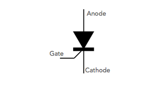
Thyristor device structure
Gate turn off thyristor, GTO
Thyristor specifications
Thyristor surge suppressor, TSS
What is a triac
Triac specifications
Diac overview
When choosing a thyristor or SCR, there are several datasheet parameters that need to be understood so that the correct device can be selected.
The various SCR / thyristor datasheet specifications and parameters are rather different to the more familiar transistor and FET specifications, but even so they are relatively straightforward.
It is worth noting that many of the thyristor specifications are also applicable for TRIACs and DIACs as well.
| Common Thyristor Specifications & Datasheet Parameters | ||
|---|---|---|
| Spec | Thyristor Specification / Parameter Details | |
| dI/dt | Maximum rise of on-state current | There is a maximum rate of rise for the on-state current during turn on. If this rate is exceeded then the device can be damaged. |
| IGM | Peak gate current | This is the maximum level of gate current that should not be exceeded. |
| IGT | Gate trigger current | This is the current required in the gate to enables the device to be triggered and to latch in its on-state provided there is sufficient anode cathode current to maintain the current flow. |
| I2t | Overcurrent protection | The I2t parameter indicates the fuse that is required for protection. It is for the 10ms overcurrent duration. |
| IT(AV) | Average on-state current | This parameter is different to the RMS current as it defines the average current rather then the RMS. RMS will give the true heating effect of the current. |
| IT(RMS) | RMS on-state current | This thyristor specification is the maximum allowed RMS current through the device. It is specified for a given temperature. Different datasheet specifications may quote ambient temperature, Ta, case temperature, Tc, or even the lead temperature, Tl. The method used for quoting the temperature normally depends upon the type of case used for the thyristor / SCR. |
| ITSM | Non-repetitive surge on-state current | As the name implies this datasheet parameter for thyristors defines the maximum peak current in the device under pulse conditions. It is necessary to look at the exact conditions for the manufacturer in question, but it is often defined for a half sine wave. The duration is specified for 50 Hz (10ms duration) and 60Hz (8.3ms duration). It is required because a surge current exceeding the maximum may cause failure of the device. |
| TJ | Junction temperature | This is the junction temperature and often the maximum junction temperature is specified in the datasheets. Calculating the thermal resistance it is possible to determine the conditions under which the maximum junction temperature is not exceeded. |
| Tstg | Storage temperature | This is the minimum temperature in which the device can be stored. |
| VDRM / VRRM | Repetitive peak off-state voltage | This parameter is the maximum peak voltage that is allowed across the device. This datasheet specification parameter should not be exceeded otherwise the device may fail. It is also always good to leave sufficient margin to allow for transients. This parameter is specified for conditions up to the maximum junction temperature. Also leakage currents (IDRM / IRRM) are also normally defined under this datasheet specification. |
| VGT | Gate trigger voltage | This is the voltage that needs to be applied between the gate and cathode to enable the gate trigger current to be reached and the device to fire. |
| VRGM | Peak reverse gate voltage | This is the maximum level of gate voltage that can be applied across the gate cathode junction without the possibility of damage resulting. It is wise to operate well below this voltage. |
Whilst there are many other thyristor specifications and parameters that are used in their datasheets, these are some of the more widely sued ones which are needed in the deign of circuits and selection of the right components.
 Written by Ian Poole .
Experienced electronics engineer and author.
More Electronic Components:
Batteries
Capacitors
Connectors
ADC
DAC
Diodes
FET
Inductors
Memory types
Phototransistor
Quartz crystals
Relays
Resistors
RF connectors
Switches
Surface mount technology
Thyristor
Transformers
Transistor
Unijunction
Valves / Tubes
Return to Components menu . . .