
Diode Valve / Vacuum Tube: operation, theory, formulas
The diode valve or vacuum tube can be used as a rectifier, and in addition to this its operation forms the basis of operation on which other forms of valve or tube are built.
Vacuum Tube / Thermionic Valves Includes:
Basics
How does a tube work
Vacuum tube electrodes
Transconductance vs amplification factor
Diode valve / tube
Triode
Tetrode
Beam Tetrode
Pentode
Nuvistor
Equivalents
Pin connections
Numbering systems
Valve sockets / bases
Travelling wave tube
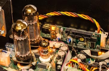
The diode valve or tube is still widely used and in years gone by, vast quantities of these devices were used.
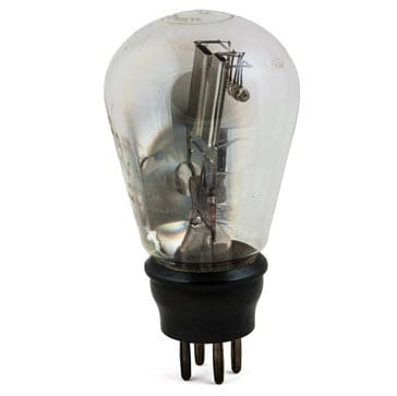
The diode vale is the most basic of all thermionic or vacuum tube devices having only two active electrodes, nevertheless it is still an important component whose operation needs to be understood if other forms of vacuum tube or thermionic valve technology are to be comprehended.
Diode valve basics
The most basic form of diode valve or vacuum tube is the diode. It consists of two conducting electrodes that are contained within an evacuated glass envelope. These are named the cathode and anode.
The cathode is heated and it is found that electrons ‘boil’ off from the electrode as a result of the energy they have as a result of the heat.
The negatively charged electrons leave a positive charge on the cathode which tends to draw them back and as a result a cloud of electrons exists around the cathode, reducing in intensity as the distance from the cathode increases. Those electrons that travel furthest have the most energy.
Nevertheless it is found that if a resistor is placed between the cathode and anode, it will be seen that a current actually flows as a result of the electrons that are given off by the cathode.

If an electron has sufficient energy to reach the anode, then it will stay there are it will not have enough energy to escape, but they can flow back to the cathode via the external resistor.
It can be seen that electron current can flow from the cathode towards the anode as a result of electrons escaping from the cathode, but electrons are unable to leave the anode.
As a result current is only able to flow in one direction. Therefore if a alternating signal is applied to the diode valve or diode tube, then it will only allow half the cycle through, thereby rectifying the signal.
If the circuit is changed slightly and a positive potential is applied to the anode, then it will attract further electrons and current will flow as a result of the battery. Again current is only able to flow in one direction.

This function can be used in rectifying line or mains input power enabling direct current, DC power to be created from an alternating current, AC input. It can also be used in detecting radio signals, and in fact this was the first used for thermionic valves or vacuum tubes. It was Ambrose Fleming from University College London who first thought of the idea of detecting signals using a diode valve.
Indirectly heated diode valve
Early diode valves used a directly heated cathode. This consisted of a heater element that also acted as the cathode. This significantly limited the operation of these devices. The use of AC for the heaters enabled a transformer to provide the heater supply directly from the incoming mains thereby reducing the cost of operation as batteries did not last long and were expensive:
- Induced hum: When AC was used to supply directly heated valves it was found the AC affected the operation of the valve and some AC could be superimposed upon the output.
- Directly heated cathode is connected to heater supply: A directly heated cathode means that the cathode is linked to the heater voltage and this prevents a common heater supply being used for several valves which may need different cathode voltages.
The solution to both issues was to use a electrically separated heater element that was used to heat a cathode. This method known as indirect heating is almost universally used for all valves whether they are diode valves, triodes or whatever.
Half wave diode valve rectifier
The simplest form of diode valve rectifier is the half wave rectifier. It only requires the use of a single diode valve rectifier. However it is not as efficient as some other forms of rectifier.

It can be seen that if an alternating waveform is applied to the diode valve, or diode tube, it conducts over half the waveform and not the other. This means that when rectifying AC waveforms it is only 50% efficient as half the waveform is used and the other half is discarded.
Full wave diode valve rectifier
In order to make use of both halves of an alternative waveform cycle, a full wave rectifier can be used. In the same way that it can be implemented with semiconductor diodes, the same can be achieved using diode valves. In fact full wave rectifier diode valves are available with one device containing the two rectifiers.

In the full wave rectifier circuit, different diodes within the rectifier handle different halves of the waveform. In this way both halves of the waveform are used. Also the fact that the time between peaks is shorter means that smoothing the waveform is much easier.
As seen in the diagram, full wave rectifier valves / tubes were available. These contained two anodes and a single cathode enabling full wave rectification to be accomplished using a single valve.
A further point to note is that power supply rectifier diodes often used a separate 5V supply, whereas the common standard for the heaters used for the equipment itself was 6.3 volts, although other voltages were often used.
Diode valve signal detector
It was through investigating radio signal detection or demodulation that the first diode valve was invented by Ambrose Fleming. In fact the diode valve detector can be used for amplitude modulated signals.
The action of the diode valve rectifier can be seen below where the amplitude modulated signal consisting of the carrier of varying amplitude is demodulated. To recover the modulation, the signal is rectified and then the carrier is removed using a capacitor as a high frequency filter.

This is a very simple but effective form of AM demodulation, although it does have its drawbacks. The levels of distortion can be high because the diode characteristic will not be totally linear, and this form of diode detector is also subject to distortion resulting from selective fading - an issue that is apparent on the frequency bands normally used for amplitude modulated transmissions.
Diode valve theory, operation & formulas
The diode valve or diode vacuum tube is relatively easy to use in a circuit to act as a power rectifier or signal detector.
However the background theory and some of the graphs and formulas can help provide an understanding of the operation of the circuits within which they may be used.
Diode anode current and voltage theory
The relationship between the current flowing in the circuit to the anode voltage is shown in the diagram below.
It can be seen that the current limits for any given cathode temperature. The reason for this is that when a sufficiently high anode voltage is reached, the anode draws away all the electrons that are emitted by the cathode. As the number of electrons emitted by the cathode is dependent upon its temperature, this becomes the overall limiting factor for a given cathode material.

With moderate or low anode voltages, the anode current is less than the maximum emission of the cathode. The reason for this is that the electrons travelling in the space between the cathode and the anode produce a negative space charge. This reduces the attraction of the positive potential on the anode.
As a result this means that the total number of electrons in transit at any given instant cannot exceed the number that will provide the negative space charge that completely neutralises the electrostatic field produced by the anode potential at the cathode surface.
Diode cathode anode potential distribution theory
If the space charge is examined across the gap between the cathode and the anode it will be seen that there is an interesting distribution of potential.
It is found that the negative charge of the electrons in the vicinity of the cathode give a slight negative potential with respect to the cathode.

Electrons from the cathode surface of the diode valve are emitted into this negative field and their velocities will vary with different electrons.
The negative field around the cathode causes the electrons to slow as they are repelled by the negative charge. Those with high velocities will penetrate this negative field, whereas those with only low velocities will be repelled, and return to the cathode surface.
Space charge limited diode anode current
It can be determined that the anode current is proportional to a 3/2 law of the voltage on the anode.
For heater style cathodes, the emission is approximately the same across the surface and therefore the total anode current for a positive anode voltage can be determined by the equation or formula:
 Written by Ian Poole .
Experienced electronics engineer and author.
More Electronic Components:
Batteries
Capacitors
Connectors
ADC
DAC
Diodes
FET
Inductors
Memory types
Phototransistor
Quartz crystals
Relays
Resistors
RF connectors
Switches
Surface mount technology
Thyristor
Transformers
Transistor
Unijunction
Valves / Tubes
Return to Components menu . . .


