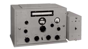
Marconi CR150 Radio Receiver
The Marconi CR150 was described as a high performance radio receiver for the day featuring a double conversion superhet circuit and many other facilities.
Marconi Receivers Includes:
Marconi CR100
Marconi CR100 circuit
Marconi CR150
Marconi CR150 circuit
R1155
Iconic radio receivers:
Summary of iconic radio receivers
Radio receiver history
Crystal radio sets
Development of the superhet radio
Radio history / timeline
The Marconi CR150 radio receiver provided improved performance over that of the CR100 which was produced in very large quantities during World War II.
Looking very much like its cousin, the Marconi CR150 radio receiver could often be mistaken, but it had a number of additional controls as well as a different specification in a number of respects.
The Marconi CR150 radio receiver offered a higher level of performance when compared to many of the other radios of the time. Boasting aspects like double conversion superheterodyne topology for improved image response and a noise limiter for use when static noice was high, it proved to be a worthy radio receiver for the needs of the time.
The CR150 is considered to be a classic radio of its time - its design was ground breaking as it was one of the first to offer a double conversion format for its electronic circuit design.
Basic CR150 radio specifications
The specifications for the Marconi CR150 give an insight into its capabilities and the way it could be used.
| CR150 Performance Summary |
||||||||||||||||||||||
|---|---|---|---|---|---|---|---|---|---|---|---|---|---|---|---|---|---|---|---|---|---|---|
| Parameter | Details | |||||||||||||||||||||
| CR150 summary | High performance double superheterodyne radio communications receiver. | |||||||||||||||||||||
| Frequency range | 2Mc/s to 60Mc/s in five bands | |||||||||||||||||||||
| Supply requirements | External power supply needed for mains and enables operation on single phase AC 50 - 60c/s at a voltage between 200 - 250V or between 90 - 140 V. Consumption approximately 90 watts. batteries may also be used: 300 V at 65mA and 6.3V at 3.7A. |
|||||||||||||||||||||
| Receiver input | 75 - 100 Ω balanced or unbalanced | |||||||||||||||||||||
| Sensitivity (average receiver) |
The manual states that by careful design the inherent noise at all frequencies below 30 Mc/s is reduced to the theoretical limit set by the thermal agitation of the first tuned circuit. in reality this translated into a specification of a 20dB signal to noise ratio on CW for signal levels of: |
|||||||||||||||||||||
| Selectivity: |
|
|||||||||||||||||||||
| Valves | 12 valve line up consisting of: EF50 (x4), X66, 6K7G (x2), DH63 (x2), L63, STV280/40 [6AM6 (x4), 6BE6 (x2), W77 (x2), 6C4 (x2), 6AM6 (x2), 6C4 (x2), CV287 for the CR160/6 - 14 valve lineup] An additional valve is used in the separate power supply: 5Z4G, for supply types 1325 / 1, /2, or /3. Metal rectifiers are used in supply types 1325/4 and /5. |
|||||||||||||||||||||
| Intermediate frequencies | 1.6 Mc/s and 465kc/s | |||||||||||||||||||||
| Receiver outputs | 3Ω loudspeaker; high resistance or low resistance telephones and 600Ω line | |||||||||||||||||||||
| Dimensions and weight | Receiver: 20½ inches width x 17 inches depth x 14 inches height and weight 61 lbs Supply unit 1325/1: 5¼ inches width x 15 inches depth x 10 inches height and weight 19 lbs Supply unit 1325/4: 5¼ inches width x 15 inches depth x 12 inches height and weight 25 lbs |
|||||||||||||||||||||
| Environmental characteristics | The radio communications receiver is defined as being suitable for operation in buildings in tropical areas | |||||||||||||||||||||
Marconi CR150 front panel controls
The front panel layout for the Marconi CR150 is relatively spacious. It contains all the controls that need to be accessed by the operator of the radio.
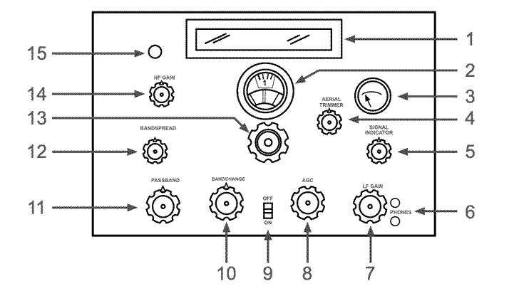
In order to understand the operation of the radio, using it for various radio communications applications, it is useful to understand what the controls are and where they are placed on the front panel.
1 - Main Frequency Indication: This indicates the main frequency for the receiver, giving a broad indication of the reception frequency. The calibration makings change as the band is changed.
2 - Logging Scale: This secondary dial provides additional accuracy over that provided by the main. It provides an equivalent length of 18 feet and 1250 divisions over that of the main frequency scale. At 20 Mc/s one scale division is equal to 12kc/s frequency change.
3 - Signal indicator : The signal indicator was a meter that not only monitored the signal strength but also the anode currents of various valves.
4 - Aerial trimmer: The aerial trimmer on the CR150 enabled the RF input circuitry to be tuned to provide the optimum signal at the frequency being received.
5 - Signal indicator switch: This switch enabled the meter to be switched to monitor the anode current levels of a number of valves in the receiver as well as being able to monitor the incoming signal level.
6 - Phones: This provided the connection for headphones. It was very useful to have this connection at the front as the CR150 receiver could be installed in a rack and any change of headphone connection needed to be made from the front.
7 - LF gain: This control enabled the audio gain or volume to be set to the required level for listening.
8 - AGC: This control enabled the AVC to be set to the required mode for the signal being received (i.e. AM or CW) and the reception conditions.
9 - On / Off: This switch provided the main on / off control for the receiver. It operated only when batteries were used. An on/off control for main supplies was provided on the individual supplies as these were connected to the incoming mains power and the switch was able to isolate the mains.
10 - Band change: This switch provided the main band change to select on which of the five bands the receiver was to operate. It was also linked tot he main frequency scale on the receiver so that the correct scale was shown.
11 - Passband: This control on the CR150 selected the passband of the IF stage. As different bandwidths are needed for different signal modulation modes and for different reception conditions, this switch was widely used when operating the receiver. Wider bandwidths were used for AM and narrower ones for CW, especially when high levels of interference were present.
12 - Bandspread: This control provides an equivalent tot he modern receiver incremental tuning. The main dial could be retained in its set position and this control could be adjusted to provide ± 4kc/s shift. It operated on the oscillator for the second conversion down from 1.6Mc/s to 465kc/s. By adjusting the frequency of this oscillator, the same shift could be achieved regardless of the frequency of the main tuning.
13 - Main tuning: This is the main tuning for the receiver which is used to set the main frequency and when searching for signals, etc.
14 HF gain: The HF gain would probably be called the RF gain. It is used to set the gain of the RF stages for the best signal to noise ratio, whilst also avoiding overloading in the later stages of the set in the presence of strong signals.
Understanding the purpose of the main controls enables the CR150 receiver to be operated in a way that enables it to provide the best performance.
Having a feel for all the controls enables the operator to respond to changing conditions rapidly and in this way ensuring that there is the best chance of maintaining reception of the required signal, and any message is not corrupted because of changing conditions.
CR150 basic circuit description
The Marconi CR150 receiver block diagram gives a good insight into its operation. With 12 valves in the line-up, plus an additional rectifier valve in the power supply unit, it gives a high level of performance.
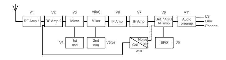
In essence the signals enter the receiver and pass through two stages of RF amplification that are optimised to provide the best noise performance.
Signals then enter the first mixer or frequency changer as it is called in the manual. This converts the signals down to a fixed 1.6 Mc/s first intermediate frequency, IF.
The first local oscillator is a free running LC oscillator that runs from a stabilised voltage to provide the frequency stability required.
The signals from the first IF stage are filtered and converted down in the next frequency changer tot he main IF at 465 kc/s. This is where the majority of the receiver gain and filtering are provided.
The signals are demodulated or "detected" using a diode rectifier using part of a double diode triode valve. Signals are also detected using a different diode in the valve for the automatic gain or volume control.
A beat frequency oscillator is coupled into the signal detector to provide an audible note for CW signals - this can obviously also be used for the demodulation of single sideband, although this mode was not in widespread use at the time of the design of this radio.
The audio from the signal detector is amplified and there are outputs for a loudspeaker, headphones and there is also a feed for a 600 ohm line.
The CR150 radio also includes a noise limiter to assist with reception of radio communications signals when there are high levels of static noise present.
Marconi CR150 variants and external power supplies
As with any item of electronic equipment, it was developed over time and a few variants were launched. Along with this, there was a variety of external power supplies that could be used.
There is some confusion over the actual specifications for the different radios, but this is possibly what they are.
| Summary of CR150 Variants / Versions |
|
|---|---|
| CR150 Variant / Version | Details |
| CR150 | Initial design of the CR150 - dual conversion with frequency range of 2 Mc/s to 60 Mc/s in 5 bands. |
| CR150/2 | As CR150 but covering 1.5 to 22 Mc/s in 4 bands. |
| CR150/3 | A redesigned version of the receiver again with dual conversions and with frequency range of 2 Mc/s to 60 Mc/s in 5 bands. It has the capability to be used for diversity reception with another CR150. The local oscillator from one receiver is used for both sets, with the LO in the second being disabled. AGC lines are also linked. |
| CR150/6 | This is an updated version of the CR150/3, adapted to incorporate more modern B9A valves. |
The CR150 used an external power supply as it had obviously not proved to be possible to incorporate a power supply in the main case for the receiver, and it was also possible that a variety of different power supply options might be needed.
| Summary of CR150 Power Supplies |
|
|---|---|
| CR150 Power Supply Type | Details |
| 1325/1 | Mains powered with 5Z4G rectifier. The transformer that appears to be used for all power supply variants appears to have taps to provide operation at 230V, 215V and 110V. Measurements: 5¼ ins wide x 15 ins deep x 10 ins high; 19lbs weight |
| 1325/2 | Mains powered with 5Z4G rectifier. Circuit same as 1325/1 according to manual. |
| 1325/3 | Mains powered with 5Z4G rectifier. Circuit same as 1325/1 according to manual. |
| 1325/4 | Uses metal rectifier. Measurements: 5¼ ins wide x 15 ins deep x 12 ins high; 25lbs weight |
| 1325/5 | Uses metal rectifier. Circuit same as 1325/4 |
The Marconi CR150 radio was a high performance radio receiver for its day. It had a number of refinements including a double conversion to improve the image performance and also a noise limiter to aid the reception of radio communications signals when high levels of static noise were present.
It was also one of the first mainline radio receivers to incorporate double conversion technology and in many respects it can be considered to be a classic radio.
 Written by Ian Poole .
Experienced electronics engineer and author.
More History:
Radio history timeline
History of the radio
Ham radio history
Coherer
Crystal radio
Magnetic detector
Spark transmitter
Morse telegraph
Valve / tube history
PN junction diode invention
Transistor
Integrated circuit
Quartz crystals
Classic radios
Mobile telecoms history
Vintage mobile phones
Return to History menu . . .