
Marconi CR100 Circuit Description
The circuit for the Marconi CR100 radio receiver included a total of 11 valves and it employed a single superheterodyne technique with a 465 kc/s intermediate frequency.
Marconi Receivers Includes:
Marconi CR100
Marconi CR100 circuit
Marconi CR150
Marconi CR150 circuit
R1155
Iconic radio receivers:
Summary of iconic radio receivers
Radio receiver history
Crystal radio sets
Development of the superhet radio
Radio history / timeline
The circuit for the CR100 followed what would not be considered to be a relatively straightforward and standard block for a communications receiver of the day.
The performance of the radio enabled it to be used in many communications applications for the British Forces during World War II and as such it was one of the iconic receivers that was manufactured in Britain during this period.
Please note: we have used the terminology, c/s, kc/s and Mc/s rather than the more modern Hz, kHz, MHz, to ensure that the text is in keeping with the terminology of the time. Also the term valve is used instead of vacuum tube as the receiver was made in the UK and this was the term used for these devices.
Basic CR100 circuit overview
The CR100 circuit used 11 valves to provide a single conversion superhet radio receiver having an IF of 465 kc/s.
The circuit incorporated a beat frequency oscillator for the reception of CW (Morse) and although single sideband SSB was not used during the war years, it could also be used for this as well.
The CR100 circuit used two valves for the RF stages, a local oscillator with a separate valve used as a mixer for stability of the oscillator.
The IF consisted of a three valve line-up with transformer coupling between stages. Selectivity was provided by the IF transformers as well as a "crystal gate" for the narrower passbands.
A double diode triode arrangement was used as the signal detector, AVC detector and first LF amplifier. A separate valve was used for the beat frequency oscillator circuit.
The signal from the detector was fed into an audio amplifier circuit using a single valve.
The final valve in the line-up for the CR100 circuit was the full wave rectifier used within the mains power supply>
Valve complement for CR100 circuit
The 11 valves used within the CR100 circuit consist of KTW62 (x7), X66, DH63, KT63, and a U50.
These valves are used in different positions within the CR100 circuit as shown in the table below.
| Valve Line-up for CR100 Radio Receiver |
||
|---|---|---|
| Valve Number | Type | Use within the circuit |
| V1 | KTW62 | 1st signal frequency amplifier |
| V2 | KTW62 | 2nd signal frequency amplifier |
| V3 | X66 | Mixer |
| V4 | KTW62 | Frequency changer oscillator |
| V5 | KTW62 | 1st IF amplifier |
| V6 | KTW62 | 2nd IF amplifier |
| V7 | KTW62 | 3rd IF amplifier |
| V8 | DH63 | Combined signal detector, AVC diode & LF amplifier |
| V9 | KT63 | Output tetrode |
| V10 | KTW62 | Beat frequency oscillator |
| V11 | U50 | Full wave rectifier |
Alternative valves
The valves detailed within the table above are not commonly available. Even the CR100 manual gives suitable alternatives.
| Alternative Substitute Valves for those in CR100 Circuit |
||
|---|---|---|
| Type | Suggested Alternative Substitutes Suggested in the CR100 Manual |
|
| KTW62 | 6K7G, 6J7G | |
| X66 | 6K8G | |
| DH63 | 6Q7G | |
| KT63 | 6F6G, 6V6G | |
| U50 | 5Y3G, 5Z4G | |
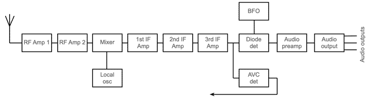
Marconi CR100 radio block diagram
The CR100 radio receiver has several circuit blocks, and it is easier to understand the operation of the whole radio communications receiver if the basic block diagram can be seen.
it can be seen that the Marconi CR100 follows a fairly standard format for a superheterodyne radio.
CR100 RF circuits
The RF circuits for the CR100 consist of the two RF amplification stages as well as the mixer.
The two RF amplifier stages use KTW62 valves. The circuits have been optimised to provide good noise performance. The gain of the first amplifier valve is sufficient that shot noise from the first valve stage dominates over that of the mixer which might otherwise have a major contribution.
The dynamic impedance of the first tuned circuit is such that it is high enough to ensure that the thermal noise here exceeds that of the first valve stage up to a frequency of about 11 Mc/s. Above this frequency, the the circuit noise has fallen below the valve noise and as a result, this dominates on Band 6 (11Mc/s to 30 Mc/s) of the receiver.
The antenna socket is connected tot he input tuning where a static leak resistor is provided to reduce static build up.
Local oscillator circuit
The local oscillator for any superheterodyne radio receiver is key to the operation of the whole radio. Its performance will determine many aspects of the overall performance, and partially that of the stability.
The local oscillator circuit comprises a KTW62 connected as a triode and having a tuned grid circuit mutually coupled an an untuned anode coil.
To enable the oscillator to always operate on the same side of the wanted incoming signal, the oscillator runs higher than the signal frequency.
Series tracker capacitors are used within the coil pack. On the three lower bands variable trimmer capacitors are used, but for the higher bands very small values of capacitance are required and these are selected during the test of the receiver.
CR100 mixer circuit.
The mixer circuit for the CR100 is based around an X66 (6K5G) valve. The local oscillator and wanted signals are applied to the inputs to the mixer.
The anode circuit for the mixer utilises an IF transformer and the signal is then applied to the first IF amplifier circuit.
CR100 IF amplifier circuits
The IF stages fort he CR100 receiver provide the majority of gain and selectivity for the receiver. There are three individual stages, each based around a KTW62 (6K7G / 6J7G) valve.
The first two stages have the AVC voltage applied to reduce the gain on strong signals.
The stages are coupled using a loosely coupled high Q transformer as this gives the best selectivity. Both the primary and secondary windings have variable permeability tuning and they use fixed capacitors on each winding.
In order to provide the variable selectivity control, the IF transformers for the second and third IF stages have a small tightly couples auxiliary winding in series with the secondary of the transformer. This is introduced when the passband switch is set to 6000c/s.
CR100 signal detector circuit
The signal detector is formed by using a third of the DH63 (6Q7G) valve. It is drive by the third IF stage.
The output from the detector is filtered to remove any RF components. It is then applied directly to a potentiometer that acts as a volume control, before the signal is applied to the audio frequency preamplifier.
Beat frequency oscillator circuit.
the circuit for the beat frequency oscillator uses an electron coupled Colpitts type circuit. This is a very standard format for oscillators and provides good performance.
The output is taken through a 30 pF capacitor tot he diode detector. The non-linearities in the diode detector enable the BFO signal to mix with the received signal to give the required beat note.
The BFO oscillator uses an inductor with an adjustable core This enables the frequency to be set to the required value during alignment.
The operator is able to adjust the frequency to suit the reception requirements using a front panel control that is mechanically linked to a variable capacitor.
CR100 AVC circuits
AVC signal is derived from the second diode in the DH63 double diode triode valve which in turn has taken its input from the output of the third IF amplifier stage.
The time constant for the AVC voltage is important as it must be slow enough to track the signal variations without being so fast that it removes the modulation from the signals.
Accordingly suitable decoupling is provided on this line to provide this, with an additional 1µF capacitor used for increasing the recovery time constant when the mode switch is placed in the CW position.
The AVC voltage is applied to both RF valves as well as to the first two intermediate frequency amplifier valves.
Audio circuits
The triode of the DH63 provide the pre-amplification for the audio signal from the signal detector.
This signal is then passed to a KT63 (6V6G / 6F6G) output tetrode for its final amplification.
An audio filter is used in the audio stages to give the narrow 100 c/s bandwidth required for some CW transmissions.
Finally the output is passed through an multi-ratio audio transformer to enable it to drive a variety of different types of output from low impedance loudspeaker to high impedance headphones, etc.
The Marconi CR100 circuit provides a very high level of performance for a radio receiver of the day. With a frequency range extending from 60 kc/s to 30 Mc/s it was able to cover the majority of frequencies used for radio communications of the day.
Although much higher levels of performance are achievable today, in the 1940s when it was used by the British Forces, it represented a very high quality radio communications receiver.
 Written by Ian Poole .
Experienced electronics engineer and author.
More History:
Radio history timeline
History of the radio
Ham radio history
Coherer
Crystal radio
Magnetic detector
Spark transmitter
Morse telegraph
Valve / tube history
PN junction diode invention
Transistor
Integrated circuit
Quartz crystals
Classic radios
Mobile telecoms history
Vintage mobile phones
Return to History menu . . .


