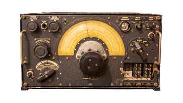
R1155 Vintage Radio Communications Receiver
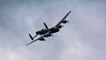
The R1155 is a vintage LF / MF / HF communications radio receiver used in WW2 with one of its main applications being within the RAF heavy bombers such as the Avro Lancaster
Marconi Receivers Includes:
Marconi CR100
Marconi CR100 circuit
Marconi CR150
Marconi CR150 circuit
R1155
Iconic radio receivers:
Summary of iconic radio receivers
Radio receiver history
Crystal radio sets
Development of the superhet radio
Radio history / timeline
The R1155 communications radio receiver was one of the mainstay radios used by the British Armed Forces in WW2. It is now considered to be a sought after vintage radio, and unmodified versions can command a good price on the collectors markets
It was paired with the T1154 transmitter and saw its main usage in the heavy bombers such as the Avro Lancaster, Handley Page Halifax, Short Sterling and also the de Havilland Mosquito and many others that were able to carry the weight of these vintage communications radio sets.
The R1155 was also used in a number of other situations, being used by some ground forces as well as on some ships.
After the war this radio was seen widely on the surplus markets and offered a very good buy for many short wave listeners and radio amateurs. Accordingly it gained a place in the memories of many people.
R1155 development & history
The R1155 radio development occurred in 1939 by the Marconi Wireless telegraph Company.
Initially it had the reference number AD.87B/8882B and it was intended to replace the much older and dated R1082 and T1083 receiver / transmitter combination.
The first installations of the new receiver transmitter combination occurred very quickly and took place in early 1940.
To meet the requirements for the numbers of these receivers and transmitters, manufacture was undertaken by a number of companies including Ekco, Plessey, Philips and the Gramophone Company (Later called EMI).
The receivers and transmitters were used after WW2 up until the 1950s, and they were even used in some commercial passenger aircraft.
During the 1960s these radios frequently appeared on the government surplus sales and accordingly they were widely available at really low prices considering what the build costs must have been.
Nowadays, these radios are considered to be vintage radios and they are occasionally seen in sales at collectors markets and the like. Most were modified, but occasionally one may be seen that is in its original state - a rare find for vintage radio collectors.
R1155 variants
There were several different variants of the R1155. Most of them were very similar although there were a few larger changes. Despite most of them being relatively similar, they did have different suffix letters to denote the different types.
| R1155 Type | Details |
|---|---|
| R1155 | Standard communications receiver |
| R1155A | Aluminium case with additional filters to prevent medium wave transmissions entering the IF stage and giving rise to interference |
| R1155B | Aluminium case and with medium wave filters as in R1155A and additional filters to prevent interference from radar |
| R1155C | Aluminium case, with medium wave and HF chokes for radar interference removal and additional modifications for HF DF (direction finding). |
| R1155D | Steel case version of the basic receiver |
| R1155E | Steel case version of the R1155A |
| R1155F | Steel case version of the R1155B |
| R1155L | Version of the R1155B but with changed frequency coverage: LF range removed and 1.5 - 3.0MHz added. |
| R1155N | Steel case version of the R1155L |
Basic R1155 specification summary
The R1155 had a reasonable specification for a radio of its day. It was designed primarily for use within heavy bomber aircraft and as such the performance reflected this operation.
It provided a good level of selectivity for its day along with reasonable selectivity and coverage of the bands that were normally needed.
| R1155 Communications Receiver Performance Summary |
|
|---|---|
| Parameter | Details |
| R1155 summary | Single conversion superheteroheterodyne radio providing coverage within the LF, MF and HF bands. |
| Frequency bands (standard) |
Band 1: 7.5 MHz - 18.5 MHz Band 2: 3.0 MHz - 7.5MHz Band 3: 600 kHz - 1500 kHz Band 4 200 kHz - 500 kHz Band 5: 75 - 200 kHz |
| Frequency bands (L & N variants) | 75 - 200 kHz band replaced with 1.5 MHz - 3.0 MHz coverage |
| Reception modes | CW, MCW & RT (radio telephony) |
| Intermediate frequency | 560 kHz |
| Sensitivity | Input of 10 microvolts at 210 kHz gives output in excess of 50 milliwants. Input of 9 microvolts at 16 MHz gives an equivalent output. |
| Selectivity | Approximately 4 to 6 kHz total bandwidth at 6dB attenuation |
| Dimensions (inches) | Length: 16&frac716; Width: 9⅜ Height: 11⅜ |
| Weight | Aluminium versions: approx 26 lbs Steel versions: approx 32 lbs |
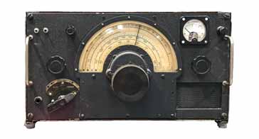
Front panel controls
The R1155 has relatively few controls for a receiver of this performance. It relies on relatively few adjustments needing to be made. It would have been relatively difficult to make some of the adjustments during the flight with general air turbulence as well as turbulence from flak and the other actions required.
The manual states that the radio has three main or fundamental controls (there are others but these were obviously not considered as being main controls). They are still on the front panel, but not used as often.
Primary controls
The primary controls were considered to be the ones that would be frequently used in normal operation.
• Tuning control The tuning control was placed in the centre of the front panel. The frequency being received is then indicated by the large semi-circular scale.
It will be noted that the scale has a number of different colours. the scale colour is based upon the transmitter T1154 coverage. Outside the transmitter coverage the scale is marked in black.
• Frequency range switch The frequency range switch has five positions and it selects the required frequency range or band for the receiver. It is located to the lower left of the main tuning dial.
• Master switch This is effectively a switch that controls how the set is operated. The switch has five positions: Omni where the IF & IF gain is manually using a ganged potentiometer control, AVC where the RF and IF gains are controlled automatically, Balance where the visual indicator is balanced before using the direction finding capability, Visual for homing by visual means, and finally ∞ is set for aural direction finding reception.
Secondary controls
There are several controls that are described as secondary controls.
• Increase volume This adjusts the bias to the RF and IF stages when the master switch is set to either Omni or ∞.
• Heterodyne switch This switches in the beat frequency oscillator for CW reception
• Meter amplitude This control is used for varying the deflection of the indicator needles when setting up the direction finding balance.
• Meter balance This control must only be used when the main switch is set to balance. It is used for balancing the direction finding meter needles.
• Meter sensitivity switch This switch on the radio front panel affects the maximum deflection of the DF indicator needles.
• Meter frequency switch This causes the LF switching oscillator to be either 80 Hz high for wireless telegraphy or 30 Hz low for radio telephony.
• Aural sense switch This is a spring loaded switch that is used for sense determination when using aural DF reception.
• Filter switch This filter is switched in to eliminate the switching frequency when monitoring visual DF. It is also used for the elimination or reduction of aircraft electrical noise and to reduce the background noise when listening to radio telephony transmissions.
It can be seen that most of the secondary front panel controls are associated with the direction finding capabilities. On board aircraft the direction finding capability would have been particularly useful when returning home after a long mission, possibly with damage from enemy action.
One notable exclusion from the front panel controls is the beat frequency oscillator frequency adjuster. This can be adjusted through a small hole on the front panel using a screwdriver. It was anticipated that this would only be adjusted periodically and it would cause more issues if it were accessible during missions where the wireless operator would be using thick gloves to combat the cold.
Circuit description
Although the R1155 circuit contains many elements associated with the direction finding capability that was so important for the bomber crews, especially when returning home after a long mission, the receiver circuit was relatively straightforward.
The radio is a ten valve single conversion superheterodyne radio. Within this line-up three valves are used to provide the direction finding capability. Accordingly seven valves were used in the basic radio line-up.
| Valve Line-up for R1155 Vintage Radio Receiver |
||
|---|---|---|
| Valve Number | Type | Use within the circuit |
| V1, V2 | VR99A Triode hexode | Visual DF switching | V3 | VR100 variable mu HF pentode | RF amplifier | V4 | VR99 triode hexode | Frequency changer and local oscillator | V5, V6 | VR100 variable mu HF pentode | IF amplifiers | V7, V8 | VR101 double diode triode | AVC, BFO, second detector, visual meter limiter & audio output | V9 | VR102, double triode | Visual meter switching | V10 | VI103 | Tuning indicator |
In terms of the circuit of the radio receiver, the incoming signal from the antenna is applied to an RF amplifier stage built around V3 which is a variable mu pentode. The band switching provides the required input matching and tuning.
The variable mu characteristic of the valve enables the gain to be controlled by varying the grid bias. This may be achieved manually or using the automatic volume control circuitry.
The frequency changer stage is based around V4 which is a triode hexode.
The output from the RF amplifier is inductively coupled to the signal grid of the hexode section of this valve with the required tuned circuits being selected by the band change switch.
The triode section of the valve acts as the first local oscillator running at a frequency 560 kHz higher than that of the incoming signal. The internal connections enable the oscillator signal to be injected into the mixer hexode circuit. It has a tuned anode circuit which is loosely coupled to an untuned grid circuit.
The output of the hexode stage is then coupled via an IF transformer to the input of the IF stage which runs at 560 kHz.
The IF stages of the receiver comprise two sections of IF amplification employing three band pass IF transformers which provide the main adjacent channel selectivity.
The primary of the IF transformer is placed in the anode circuit of the preceding stages and then the secondary is applied to the grid circuit of the following stage. The circuit is placed in series wit the grid bias resistor which is bypassed to RF using a capacitor.
For the detector stage, the output from the last IF amplifier is coupled to the detector using the final IF transformer. This output is taken to one diode of the double diode triode valve, V8.
The diode acts as the detector and the triode acts as the output valve.
The second diode in the valve envelope is used with the DF circuitry.
The R1155 vintage radio communications receiver is a fine example of a radio used in WW2. Normally used in heavy bombers alongside the T1154 transmitter, this radio was used extensively and also had the added capability of direction finding that was particularly useful when crews were returning home after a long mission.
Although many of these radios appeared on the surplus markets in the 1960s, they are not widely seen these days and obtaining an unmodified version can be difficult. When these radios do appear in an un-modified state, they can fetch a premium on the vintage radio markets.
 Written by Ian Poole .
Experienced electronics engineer and author.
More History:
Radio history timeline
History of the radio
Ham radio history
Coherer
Crystal radio
Magnetic detector
Spark transmitter
Morse telegraph
Valve / tube history
PN junction diode invention
Transistor
Integrated circuit
Quartz crystals
Classic radios
Mobile telecoms history
Vintage mobile phones
Return to History menu . . .