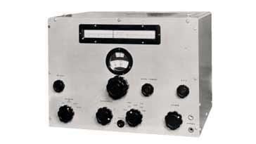
Marconi CR100 Communications Radio Receiver
The Marconi CR100 was one of the classic radio receivers used by British Forces during the Second World War covering 60 kHz to 30 MHz.
Marconi Receivers Includes:
Marconi CR100
Marconi CR100 circuit
Marconi CR150
Marconi CR150 circuit
R1155
Iconic radio receivers:
Summary of iconic radio receivers
Radio receiver history
Crystal radio sets
Development of the superhet radio
Radio history / timeline
The CR100 radio receiver is one of the classic vintage radio receivers dating back to World War II where it was widely used by the British Forces. This classic radio provided to be invaluable for many radio communications applications int hese times.
Although it may lack some of the style and pizzazz for receivers like the RCA AR88, the CR100 was a reliable workhorse that was used by the Army, Royal Navy and the Royal Air Force for their radio communications.
Even after the war it was widely used, and then as surplus supplies became available, it was picked up by radio enthusiasts: radio amateur or radio hams, short wave listeners and anyone who wanted a good reliable radio receiver coving frequencies up to 30 MHz.
The Marconi CR100 radio receiver provided what was needed at the time: a good receiver with good performance for the time and without any unnecessary extras that might not be needed.
CR100 versions / variants
Over its lifetime several versions of the Marconi CR100 were produced and it also went under another number for some services. This can be a little confusing at times and therefore the numbers are given below.
| Summary of CR100 Variants / Versions |
||
|---|---|---|
| CR100 Variant / Version | Other numbers | Details |
| CR100 | - | This was the basic radio designation and was used for the prototype |
| CR100/1 | B28, W2835 | Widely used receiver, used mainly by Admiralty. Had high phone level with jacks and 1000 Ohm loudspeaker |
| CR100/2 | R1297 | Used by Army, RAF and other services. It had coaxial antenna input and a side tone facility for operation with a transmitter. |
| CR100/3 | This designation was superseded by the CR100/5 | |
| CR100/4 | B28, W2835A | This had a few additions over the basic CR100/1 |
| CR100/5 | B28, W2835B | This had coaxial fittings for the aerial input as well as an improved rear terminal board. |
| CR100/6 | B35, W8126 | Special version for use with aerial tuner - widely used for direction finding by the Navy |
| CR100/7 | B28, W2835D | This version of the CR100 had a noise limiter added an an additional IF output socket. |
| CR100/8 | - | Used a 3 Ohm loudspeaker and updated headphone jacks. |
The Marconi CR100 versions /1, /4, /5, /6, /7 and /8 were used by the Royal Navy where they were referred to as the Admiralty Model B28. They were the standard MF / HF radio communications receivers that were used on the Royal Navy and Royal Canadian Navy ships in World War II.
Numbers beginning B were generally Admiralty (Royal Navy) numbers, and those beginning W tended to be RAF.
CR100 performance & circuit overview
The CR100 provided a very good level of performance for its day. It was designed to provide a good level of performance, and one that could be easily operated by relatively non-technical people for various aspects of radio communciations.
| CR100 Performance Summary |
|
|---|---|
| Parameter | Details |
| CR100 summary | Self contained superheterodyne radio communications receiver with AVC for use on CW and phone reception. |
| Frequency range | 60 kc/s to 420 kc/s and 500 kc/s to 30 Mc/s in six bands |
| Supply requirements | (1) HT & LT batteries (1) HT 250 volts 100mA reduced to nbsp; HT160 volts 60 mA if desired LT 6 volts 4 amps or (2) Battery and rotary converter 6 volts 8 amps total supply (2)AC supplies 200 / 250 volts 50c/s 85 watts. |
| Receiver input | 100 ohms, balanced or balanced or high impedance aerial. |
| Sensitivity (average receiver) |
For 20dB signal to noise ratio on CW 60 kc/s to 11 Mc/s 1 to 2 µV 11 Mc/s to 30 Mc/s 1.5 to 4 µV |
| Valves | 11 valve line up consisting of: KTW62 (x7), X66, DH63, KT63, U50 |
| Receiver outputs | Loudspeaker (3 ohms or 1000 ohms) 2 watts maximum approx. Line (600 ohms) of the order of 2 mW Phones (high or low resistance) depending upon impedance of phones and receiver edition |
| Dimensions and weight | Width 16 ins; Depth 16 ½ ins; Height 12 ½ ins Weight 82 lb. |
Marconi CR100 front panel controls
The CR100 has a number of controls on the front panel as would be expected for an HF communications receivers.
The controls and dial are all accessible on what is a good uncluttered panel with all the required controls easily accessible.
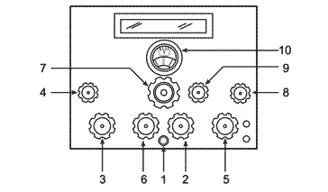
In total there is a total of nine controls and on top of this are the frequency indicator dials and scales.
1 - Main Switch: This is the main power switch for the receiver. When switching on, the manual suggests waiting for a few minutes for the receiver valves to warm up. It is also not in operation for situations where the CR100 is powered from batteries. This should be switched separately and account will need to be taken of both HT and LT.
2 - AVC: This sets the automatic volume control mode for the receiver. Today this would be referred to the as an automatic gain control or AGC as it alters the gain of the receiver and prevents overloading, etc within the radio.
Modes are available for manual or automatic and for modulated signals like AM or for Morse, CW for which different time constants on the AGC are needed.
3 - Passband Switch: This is effectively the selectivity for the receiver. Different levels of selectivity are available as marked on the panel: 6000 c/s; 3000 c/s; 1200 c/s; 300 c/s & 100 c/s.
4 - HF Gain: This control sets the gain of the front end stages. If it is set too high, then the receiver could overload on strong signal, but too low and the weaker signals will not be hear. the control of the HF gain, often called RF gain, allows for the optimum setting to be made for the reception of a given signal.
5 - LF Gain: This is the audio gain control for the receiver and it allows for the audio level to be set for a suitable level for the reception needed - speaker level or for listening via headphones.
6 - Band change switch: This switch is used for selecting the required band for operation. Overall there are six different bands that can be selected to provide the required coverage.
7 - Main Tuning: This control on the CR100 provides the main tuning for the receiver. As the receiver is tuned, so the dials will follow the adjustments to give an indication of the frequency to which the receiver is tuned. Although nowhere near as accurate as the tuning indications we have on receivers today, it provided a good indication for the day. Other means, such was crystal controlled wave meters could be used where a more accurate indication of frequency was required.
8 - BFO: The BFO or beat frequency oscillator adjustment enabled the exact frequency of this oscillator to be adjusted. It operated at the intermediate frequency, or IF of the CR100 and as a result its frequency needed to be adjusted relative to t e IF passband and operation required and then left alone.
The CR100 manual suggests adjusting it after the receiver has properly warmed up, i.e. after 15 minutes or more from switch on, and then leaving it set.
9 - Aerial Trimmer: The aerial trimmer, or antenna trimmer enabled the RF stages to be adjusted for optimum tuning at the frequency of operation. It was used to peak the strength of the signal at the actual frequency of operation.
These are the controls that are available for the operator to use on the CR100 radio receiver. They enable all the adjustments to be made that are needed for the reception of signals by the radio receiver.
Basic circuit description
The Marconi CR100 follows a relatively standard topology for radio communications receivers of the time.
It employs a single conversion from the RF input down to am intermediate frequency of 465 kc/s.
The receiver provides two stages of RF amplification prior tot he first RF mixer which converts the signal frequency down to the intermediate frequency.
The IF stages consist of three stages of amplification, and it uses tuned transformers and an IF crystal gate, as it is referred to, to provide the selectivity.
The final IF stage uses a double diode triode valve to give amplification as well as signal detection.
A separate circuit is used for the beat frequency oscillator, and a feed from this oscillator is taken to the signal detector for demodulation of CW (Morse) signals. SSB was only used later, but the BFO would be used for this.
A steady output voltage was taken from the diode detector to enable the operation of the AVC.
Audio from the signal detector is applied to a triode LF preamplifier and then the final tetrode audio output valve. A final valve, U50, is used for the rectification of the mains power input to the receiver.
the Marconi CR100 communications radio receiver, was a classic radio receiver of the war years. It was produced in large quantities and used for everything from ships radios to those used in ground listening stations. They were also widely used for the "Y" stations that were used to intercept the Nazi radio communications messages which were then sent on to Bletchley Park for decryption.
The CR100, was a no-frills radio communications receiver for its day. It did not have the looks of other radios, but performed well and provided good service for those who used them, and this made it a classic radio of its time.
 Written by Ian Poole .
Experienced electronics engineer and author.
More History:
Radio history timeline
History of the radio
Ham radio history
Coherer
Crystal radio
Magnetic detector
Spark transmitter
Morse telegraph
Valve / tube history
PN junction diode invention
Transistor
Integrated circuit
Quartz crystals
Classic radios
Mobile telecoms history
Vintage mobile phones
Return to History menu . . .