Marconi CR150 Radio Circuit & Block Diagram
The circuit for the Marconi CR150 offers a double conversion capability to provide improved image rejection along with selectable passband and many other features.
Marconi Receivers Includes:
Marconi CR100
Marconi CR100 circuit
Marconi CR150
Marconi CR150 circuit
R1155
Iconic radio receivers:
Summary of iconic radio receivers
Radio receiver history
Crystal radio sets
Development of the superhet radio
Radio history / timeline
The Marconi CR150 circuit diagram shows that it is a high performance (for the day) radio communications receive.
From the block diagram, it can be seen that the CR150 was a dual conversion receiver with a variable first local oscillator, and static second oscillator. The intermediate frequencies were 1.6 Mc/s and then 465kc/s.
The aim of the double conversion was to give significantly improved image rejection performance. This would provide lower levels of interference to wanted signals and better identification of what signals were real and which were image signals.
CR150 valve lineup
The circuit for the Marconi CR150 radio used a variety of valves and unlike the CR100, the CR150 relied heavily on the EF50 as a pentode for amplification in the RF and IF stages.
The CR150 circuit incorporated a 12 valves within the receiver cabinet, and there was a further rectifier valve in the power supply if a valve power supply, rather than the metal rectifier was used.
| Valve Line-up for CR150 Radio Receiver |
||
|---|---|---|
| Valve Number | Type | Use within the circuit |
| V1 | EF50 | 1st signal frequency amplifier [pentode] |
| V2 | EF50 | 2nd signal frequency amplifier [pentode] |
| V3 | EF50 | First frequency changer (mixer) [pentode] |
| V4 | EF50 | Frequency changer oscillator [pentode] |
| V5 | X66 | Second oscillator and frequency changer [triode hexode] |
| V6 | EF50 | IF amplifier |
| V7 | EF50 | IF amplifier |
| V8 | DH63 | Combined signal detector, AVC diode & LF amplifier |
| V9 | 6K7G | Beat frequency oscillator [pentode] |
| V10 | DH63 | Noise limited & calibration oscillator |
| V11 | L63 | LF output [triode] |
| V12 | STV280/40 | Voltage stabiliser |
| External power supply type 1325/1, /2, & /3 * | ||
| V1 | 5Z4G | Double diode mains rectifier |
* Power supply types 1325/4 and /5 use a metal rectifier.
The EF50 valve was a major advance on other valves that had been available at the time. It was an early all-glass wideband remote cutoff pentode which had been designed by Philips in 1938.
It is an interesting story in itself of how essential elements of the production line for these valves had to be transferred from Holland where it had been manufactured to England as the Nazis overran Holland in 1940.
As the valve was essential for the operation of the British radar sets, it was essential to keep production going. Once they were produced in Britain, they were also very useful for communications receivers like the Marconi CR150 that had a frequency response that extended to 60 Mc/s, as well as other items of high frequency equipment.
Marconi CR150 block diagram
The Marconi CR150 receiver block diagram gives a good insight into its operation. With 12 valves in the line-up, plus an additional rectifier valve in the power supply unit, it gave a high level of performance for its day.
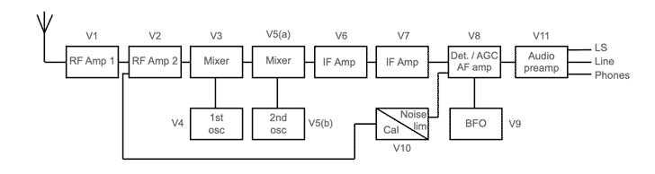
The signals entered the receiver and passed through two stages of RF amplification with the associated filtering. These stages were are optimised to provide the best noise performance.
Signals then entered the first mixer or frequency changer as it was called in the manual. This converted the signals down to a fixed 1.6 Mc/s first intermediate frequency, IF.
The first local oscillator was a free running LC oscillator that ran from a stabilised voltage to provide the frequency stability required.
The signals from the first IF stage were filtered and converted down in the next frequency changer to the main IF at 465 kc/s.
The signals were demodulated or "detected" using a diode rectifier using part of a double diode triode valve. Signals were also detected using a different diode in the valve for the automatic gain control.
A beat frequency oscillator was coupled into the signal detector to provide an audible note for CW signals - this could obviously also be used for the demodulation of single sideband, although this mode was not in widespread use at the time of the design of this radio.
The audio from the signal detector was amplified and there were outputs for a loudspeaker, headphones and there was also a feed for a 600 ohm line.
The CR150 radio also included a noise limiter to assist with reception of radio communications signals when there are high levels of static noise present.
There were also circuits included to enable diversity reception using a different CR150. This would have been used with a different antenna to provide better overall reception of a signal.
RF circuits
The RF amplifier section utilised two stages, both based around an EF50 pentode to provide high level of gain, whilst also optimising the pre-mixer noise performance.
There were tuned circuits between the antenna and the input of the first amplifier as well as between the two amplifiers and at the input to the mixer. These gave a high level of rejection for off channel signals and especially the image signal.
The amplifiers were subject to the AGC line which reduced the gain when strong signals were present.
First oscillator circuit
There was a considerable investment in ensuring the stability of the first local oscillator was as stable as possible. The mechanical stability was a key aspect with the tuning capacitor having a robust frame as well as the coils for some bands being wound on ceramic formers. The ceramic formers enabled coils to have a very high Q coils and this helps reduce drift.
In addition to this a specific capacitor was introduced into the resonant circuit to compensate any drift caused by temperature effects.
Although the receiver would normally use the LC tuned variable frequency oscillator, it was also possible to use a crystal to determine the frequency. In this way the CR150 circuit would operate on a single fixed frequency which would be very stable. This could be very useful for some specific applications.
CR150 intermediate frequency circuits
The first IF operated at 1600kc/s. having the high frequency IF meant that the frequency difference between the wanted reception frequency and the image was high, i.e. twice the IF of 1600kc/s which is 3200kc/s or 3.2Mc/s.
The output of the first IF was taken directly to the second frequency changer of mixer. The valve for this was a triode hexode providing both mixing and oscillator functions for this frequency conversion.
The local oscillator for this frequency conversion operated at 1135kc/s and could be varied by ± 4kc/s under the control of a front panel trimmer capacitor. This bandspread control was sufficient to tune a signal across the selectivity curve of the radio receiver.
The second IF was at a frequency of 465kc/s and provided a major part of the gain of the whole receiver. It also provided the overall adjacent channel selectivity for the set except for the 100c/s narrowest bandwidth.
The two widest passbands were determined by the LC tuned IF transformers and their coupling. A crystal filter with two crystals was used to reduce the passband to 3 000 c/s, and a further crystal filter to reduce this to 1000c/s. The final narrow bandwidth of 100c/s was implemented using an audio filter in addition to both crystal filters.
Signal detection and BFO
A single diode detector was used for the detection or demodulation of amplitude modulated signals. A beat frequency oscillator was introduced into the circuit for CW (it would also work for single sideband radio communications although this was not widely used at the time of the introduction of the radio). The BFO was electron coupled to the signal diode when in operation.
The beat frequency oscillator had to be efficiently screened to prevent any harmonics interfering with the signal frequency input.
CR150 audio circuits
The audio circuits for the CR150 radio communications receiver were relatively straightforward and accordingly they do not warrant a long description.
The output from the diode detector was passed to the input of a triode amplifier that used part of V8, the DH63 double diode triode which was also used as the signal detector.
The output from this was then used to drive the output valve, V11, an L63 pentode valve. There was an output audio transformer in the anode circuit and this transformed the output for a 3Ω loudspeaker, for high or low impedance headphones or a 600 Ω line.
The audio section also included a narrow band 100c/s audio filter. It is this filter on top of the crystal filters that provided the 100c/s receiver bandwidth for the reception of CW in difficult conditions.
Automatic gain control circuits
The automatic gain circuit for the CR150 took its feed from the final intermediate frequency transformer. It used one of the sections of V8, the DH63 double diode triode to rectify the signal. The resulting output was applied to a filter circuit to give the required time constants.
Different time constants were required for different types of transmission and different conditions. The different time constants and operation were selected from the front panel AGC switch.
Noise limiter
Unlike the CR100, the more advanced circuitry for the CR150 radio communications receiver incorporated a noise limiter circuit. When operating in areas of high static, very large bursts of noise could be received and they resulted in very loud audio "cracks" or bangs which could be disturbing for the operator. The noise limiter circuit sought to limit these to more acceptable levels.
The noise limier circuit was based around V10, a DH63 double diode triode. The double diode was used to conductor in either direction once a certain voltage had been exceeded. In this way it clipped both sides of the audio waveform once a certain voltage had been reached.
This would mean that signals which were a normal level were left unaltered, but if a sharp high level transient was received, then its level would be limited to an acceptable value.
Crystal calibrator
<[>The triode section of V10 the DH63 double diode triode acts as a crystal oscillator circuit using an AT cut crystal. The AT cut crystal has a low temperature coefficient and therefore its frequency remains more constant over a wide temperature range.The crystal oscillator circuit operates at a fundamental frequency of 500kc/s and there are strong harmonics present which can be received up to 30 Mc/s and beyond.
Receiving these signals enables the frequency calibration of the receiver to be checked at intervals of 500kc/s, and this was often a key requirement whens setting up radio communications links, or monitoring other stations.
The Marconi CR150 receiver circuit provides a very high level of performance for a receiver of its day. The double conversion superhet technology enables low levels of image signals, whilst the RF input gives relatively sharp tuning and significant gain to provide a good signal to noise ratio.
The second IF has a series of crystal filters that mean the adjacent channel selectivity is good, and well beyond that of many other receivers of the day.
The CR150 radio communications receiver also offered the capability of diversity working for more specialised applications.
Although very few of these receivers are seen on the market these days, they nevertheless represented a milestone in receiver technology and development of the day.
 Written by Ian Poole .
Experienced electronics engineer and author.
More History:
Radio history timeline
History of the radio
Ham radio history
Coherer
Crystal radio
Magnetic detector
Spark transmitter
Morse telegraph
Valve / tube history
PN junction diode invention
Transistor
Integrated circuit
Quartz crystals
Classic radios
Mobile telecoms history
Vintage mobile phones
Return to History menu . . .