
What is a Doherty Amplifier
The Doherty amplifier is used in many areas where high efficiency RF power amplifiers are needed for high peak to average power ratio uses.
Home » Radio & RF technology » this page
Doherty Amplifier Includes:
Doherty amplifier
Design techniques
Many modern radio communications systems use high order QAM transmissions which have a high peak to average power ratio and require a linear RF amplifier. This normally leads to low efficiency in the final RF power amplifiers.
The Doherty amplifier is able to provide a means of linearity whilst being able to provide a significant improvement in efficiency.
The Doherty power amplifier is an RF design of a class B amplifier configuration that achieves high efficiency by having two amplifier sections. One amplifier section caters for the lower amplitude signal situations. A second amplifier is then brought in to use to provide the capability to meet the higher level signals conditions without running into compression.
In this way the Doherty amplifier is able to provide both linearity and efficiency.
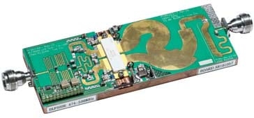
Courtesy Ampleon
Doherty power amplifier development
The concept for the Doherty power amplifier configuration was invented by William H. Doherty of Bell Telephone Laboratories in 1936.
Although the initial concept of the RF design for the amplifier was developed in the days of vacuum tube / thermionic valves, the Doherty amplifier met the need for transmitters running high power, while still needing to maintain reasonable power efficiency levels to reduce costs, heat dissipation and running costs. Vacuum tubes / thermionic valves were very power hungry and therefore any improvement in efficiency would reduce the power consumption, and also the need for quite so power capability, thereby reducing cost and space.
The first RF circuit design for a Doherty amplifier used two vacuum tube amplifiers, both biased in Class B and able to deliver tens of kilowatts to the antenna.
.Requirement for Doherty amplifier
The Doherty amplifier is now finding a huge amount of use for RF circuit designs within the base station transmitters for cellular telecommunications systems as well as many other radio communication systems where higher power levels and good levels of efficiency are required. With many millions of base stations around the globe, cost savings from efficiency improvements are huge.
The Doherty power amplifier is able to provide improvements in amplifier efficiency while enabling it to remain in a linear operating mode. With mobile communications / wireless communications systems needing to reduce power consumption and improve overall efficiency to maintain they ecological credentials, reducing power consumption is a key requirement.
With the increasing peak to average power ratios being found with the newer modulation formats being used for systems like 3G, 4G, and 5G mobile communications as well as other radio communications systems, linearity is key for the data errors to be minimised.
However normal linear amplifiers are not at all efficient, and techniques like the Doherty principle are needed to ensure the power amplifiers for radio communications and wireless communications systems remain efficient.
In basic terms, the efficiency is defined as the output power divided by the input power, but this is affected by a number of issues including the peak to average power ratio.
To look at how the peak to average power ratio affects efficiency it is necessary to look at the operation of an amplifier.
When operating in a linear mode, the output device must always be in conduction, with the output voltage rising and falling between the two limits.

When operating in this mode, often called Class A, the maximum theoretical efficiency that can be achieved is 50%, but in real systems the levels that are achieved are always below this. Circuit losses are one reason, but another is that the signal may not be reaching the maximum levels for the RF amplifier.
To achieve better efficiency levels, it is possible to drive the amplifier into compression. Much greater levels of efficiency can be achieved using this approach. Signals like frequency modulation, FM that have no amplitude constituent are not distorted by this. The only signal degradation is that additional harmonics of the fundamental carrier are generated, but these can be filtered out using RF filters.
Unfortunately when a signal modulated with an amplitude component is applied to an amplifier run in compression, amplitude distortion results. At the limit, when an amplifier is run in a fully limiting mode, then all the amplitude components are stripped off.
For data transmission systems that are used today like UMTS, HSPA, 4G LTE, 5G, etc, the RF waveforms that are used incorporate an amplitude component in addition to the phase elements and therefore they require a linear RF amplifier.
The situation becomes worse when the peak to average ratio increases because the amplifier has to be able to accommodate the peaks whilst remaining linear in its operation. To achieve this the amplifier is only able to run at a very low average power and this reduces the efficiency.

Doherty amplifier basics & theory
The Doherty power amplifier is able to accommodate signals with higher peak to average power ratios whilst still retaining a good level of power efficiency. It achieves this by using two amplifier circuits within the one overall RF amplifier to accommodate the different conditions experienced.
They are biased differently and provide different functions.
- Carrier amplifier: This section of the overall Doherty amplifier normally operates in class A or AB and provides gain at any power level. It is particularly aimed at carrying what may be termed the average amplitude signal levels
- Peaking amplifier: This second RF amplifier comes in to play when the carrier amplifier is getting towards its limits. The peaking amplifier provides the extra power capability that the carrier amplifier on its own cannot provide.
One of the keys to the operation of the Doherty amplifier is to get the peaking amplifier section to operate only when it is required. If it runs all the time, then the efficiency savings will not be gained. The aim is for the carrier amplifier to run at all times and for the peaking amplifier to enter operation just before the carrier amplifier starts to run into compression.

In addition to the amplifiers themselves, the RF circuit design for the Doherty amplifier configuration requires an RF splitter and a combiner. These items enable the power to be directed to the two amplifiers and then the output from them to be summed to provide the composite output. The splitter and combiner also need to accommodate the phase and matching requirements for the two circuits.
Doherty amplifier types
There is a number of different types of Doherty power amplifier that can be designed:
- Symmetric Doherty amplifier: This is the more straightforward approach for the RF circuit design of a Doherty amplifier. It uses two identical RF amplifiers in the circuit, but does not offer quite the performance of the second type.
- Asymmetric Doherty amplifier : The asymmetric Doherty is the most widely used format for the RF circuit design of this type of amplifier. It has two different RF amplifiers within the overall block. In this approach the peaking amplifier has a higher power capability. This means that it can accommodate the signal peaks, leaving the lower power amplifier to cater more effectively for the lower signal levels. This approach enables much better performance levels to be achieved.
- Digital Doherty amplifier : Traditionally analogue techniques have been applied to Doherty amplifiers, but the different bias schemes used for the different amplifiers and phase offsets have limited bandwidth and efficient - Doherty amplifiers are challenging to design. Developments of Doherty amplifiers have been undertaken using digital techniques.
Using a digital Doherty amplifier approach it is possible to use a lookup table for the dynamic phase alignment between the carrier and the peaking amplifiers. Digital pre-distortion, DPD is then used with an open loop amplifier for the peaking amplifier signal path. By using DPD, the amplitude-modulation / phase-modulation response of the peaking amplifier becomes relatively constant. This means that any phase difference issues between the two transmission line paths can be corrected relatively easily by adding a constant phase shift at the input of the phase-lagging signal path.
Digital Doherty amplifiers are not widely used yet, but the digital Doherty approach overcomes many of the issues of the totally linear methodology and can provide some significant improvements.
Doherty amplifier advantages & disadvantages
When considering the use of a Doherty amplifier it is necessary to understand the major advantages and disadvantages.
Doherty amplifier advantages
- Enables higher efficiency levels to be achieved.
- Technology is not as complicated as envelope tracking which also improves RF amplifier efficiency
Doherty amplifier disadvantages
- Difficult to maintain phase shifts of splitters over a wide bandwidth and therefore Doherty amplifier can only be used over a limited bandwidth.
- Higher cost than a single amplifier.
- Design is not easy to undertake and obtain optimum performance.
The Doherty amplifier does have its drawbacks, but is being used increasingly within mobile phone base stations and other wireless communications and general radio communications systems. Here the Doherty amplifier is able to provide the improved efficiency that is required - cellular networks can consume huge amounts of power and operator seek to reduce this to reduce costs. In addition to this, the amplifier needs to be linear to prevent distortion and other effects like spectral regrowth that can occur, especially if the amplifier is non-linear.
 Written by Ian Poole .
Experienced electronics engineer and author.
More Essential Radio Topics:
Radio Signals
Modulation types & techniques
Amplitude modulation
Frequency modulation
OFDM
RF mixing
Phase locked loops
Frequency synthesizers
Passive intermodulation
RF attenuators
RF filters
RF circulator
Radio receiver types
Superhet radio
Receiver selectivity
Receiver sensitivity
Receiver strong signal handling
Receiver dynamic range
Return to Radio topics menu . . .


