Amplitude Modulation Theory & Equations
Amplitude modulation and its sidebands can be easily explained using trigonometrical equations which reveal how the sidebands are generated.
Home » Radio & RF technology » this page
Amplitude Modulation, AM Tutorial Includes:
Amplitude modulation, AM
AM basic theory & formulas
AM bandwidth & sidebands
Modulation index & depth
AM efficiency
AM demodulation / detection
Diode detector
Synchronous detector
AM modulators
Single sideband, SSB
SSB demodulation
Modulation formats:
Modulation types & techniques
Frequency modulation
Phase modulation
Quadrature amplitude modulation
The basic theory and equations behind amplitude modulation are relatively straightforward and can be handled using straightforward trigonometric calculations and manipulation.
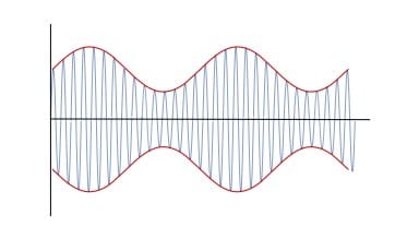
Essentially an amplitude modulated wave consists of a radio frequency carrier - a sine wave at one frequency, typically in the radio frequency portion of the spectrum. A modulating wave, which in theory could be another sine wave, typically at a lower audio frequency is superimposed upon the carrier.
The two signals are multiplied together and the theory shows how they interact to create the carrier and two sidebands.
The equations for the simple example of the a single tone used for modulation can be expanded to show how the signal will appear of a typical sound consisting of many frequencies is used to modulated the carrier.
Amplitude modulation theory & equations
It is possible to look at the theory of the generation of an amplitude modulated signal in four steps:
- Carrier signal
- Modulating signal
- Overall modulated signal for a single tone
- Expansion to cover a typical audio signal
These steps will be covered in greater details below:
1. Carrier signal equations
Looking at the theory, it is possible to describe the carrier in terms of a sine wave as follows:
Where:
carrier frequency in Hertz is equal to ωc / 2 π
C is the carrier amplitude
φ is the phase of the signal at the start of the reference time
Both C and φ can be omitted to simplify the equation by changing C to "1" and φ to "0".
2. Modulating signal equations
The modulating waveform can either be a single tone. This can be represented by a cosine waveform, or the modulating waveform could be a wide variety of frequencies - these can be represented by a series of cosine waveforms added together in a linear fashion.
For the initial look at how the signal is formed, it is easiest to look at the equation for a simple single tone waveform and then expand the concept to cover the more normal case. Take a single tone waveform:
Where:
modulating signal frequency in Hertz is equal to ωm / 2 π
M is the carrier amplitude
φ is the phase of the signal at the start of the reference time
Both C and φ can be omitted to simplify the equation by changing C to "1" and φ to "0".
It is worth noting that normally the modulating signal frequency is well below that of the carrier frequency.
3. Overall modulated signal for a single tone
The equation for the overall modulated signal is obtained by multiplying the carrier and the modulating signal together.
The constant A is required as it represents the amplitude of the waveform.
Substituting in the individual relationships for the carrier and modulating signal, the overall signal becomes:
The trigonometry can then be expanded out to give an equation that includes the components of the signal:
In this theory, three terms can be seen which represent the carrier, and upper and lower sidebands:
Carrier: A . sin (ωc t)
Upper sideband: A . M/2 [ sin ((ωc + ωm) t + φ)
Lower sideband: A . M/2 [ sin ((ωc - ωm) t - φ)
Note also that the sidebands are separated from the carrier by a frequency equal to that of the tone.
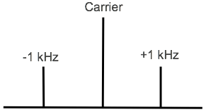
It can be seen that for a case where there is 100% modulation, i.e. M = 1, and where the carrier is not suppressed, i.e. A = 1, then the sidebands have half the value of the carrier, i.e. a quarter of the power each.
4. Expansion to cover a typical audio signal
With the basic concept of modulation and the resultant sidebands established, the same principles can be applied to the more complicated cases of modulation using speech, music or other audio sounds.
Theory can be used to break down a sound into a series of sinusoidal signals. These are linearly added to each other to form the audio spectrum of the modulating signal.
The spectrum of the modulating signal extends out either side from the carrier, one sideband is the mirror of the other, with the lowest frequencies closest to the carrier, and highest furthest away.
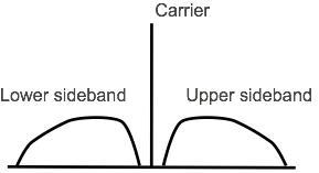
with an audio signal containing many frequencies
It can be seen that the audio signal covers a band of frequencies either side of the main carrier. The theory and equations show that furthest extent of the sidebands from the carrier corresponds to the highest frequency of the modulating tone for the amplitude modulated signal.
Seeing a little of the theory and mathematics behind amplitude modulation gives a better understanding of how it works. This can then be applied to use this type of mode to its best, whether as amplitude modulation, single sideband, or even giving abetter understanding of how QAM operates. Understanding how the modulating waveform not only generates undulations of the envelope, but also generates sidebands, etc enables the basic concepts behind AM to be understood.
 Written by Ian Poole .
Experienced electronics engineer and author.
More Essential Radio Topics:
Radio Signals
Modulation types & techniques
Amplitude modulation
Frequency modulation
OFDM
RF mixing
Phase locked loops
Frequency synthesizers
Passive intermodulation
RF attenuators
RF filters
RF circulator
Radio receiver types
Superhet radio
Receiver selectivity
Receiver sensitivity
Receiver strong signal handling
Receiver dynamic range
Return to Radio topics menu . . .