
SMA RF Attenuator
SMA RF attenuators are used in many areas of RF electronics as they are compact, easy to use.
Home » Radio & RF technology » this page
RF Attenuators Includes:
Attenuator basics
Attenuator specs
Resistive attenuator design
Attenuator resistor values table
Balanced resistive attenuator pads
Variable PIN diode attenuator
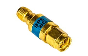
SMA attenuator
SMA attenuators are easily available and can easily be dropped into a circuit that uses SMA connectors.
The SMA attenuators have SMA connections - SMA male at one end and SMA female at the other. In this way, the SMA attenuator can drop into an existing system using SMA connectors or for new circuits it can keep the same connector type throughout enabling a reduction in different types of connector.
The other advantage of SMA connectors is that they are compact - if no additional heatsink is needed, they take up little more space than the two connectors themselves.
SMA connectors
SMA connectors are widely used, especially for microwave RF applications. Their small size and high RF performance makes them ideal for connections between modules or assemblies within units of RF systems. The small diameter coax used with them means that coax losses are comparatively high, but for short interconnections this is quite acceptable. To provide the required RF performance, these connectors are often gold plated.
The connectors have a threaded outer coupling interface that has a hexagonal shape, allowing it to be tightened with a spanner. Special torque spanners are available to enable them to be tightened to the correct tightness, allowing a good connection to be made without over-tightening them. The torque required is typically 8 inch pounds.
SMA connectors are designed to have a constant have a 50 ohm impedance across the connector. The SMA connectors are designed and specified for operation up to 12.4 GHz, although many high quality versions are useable up to 18 GHz. Also it may be possible to sue them to 24 GHz with a greater level of loss and a lower return loss. Cheap versions of these connectors will not have the same performance, despite what may often be claimed, however they may still be quite acceptable for many applications.
SMA attenuators - values
SMA attenuators are available with a variety of different levels of attenuation. Figures for some of the more common values are given in the table of attenuation vs power ratio and current / voltage.
| Performance Parameters for Common SMA RF Attenuator Variants |
||
|---|---|---|
| SMA attenuator attenuation, dB | Power Ratio | Current or Voltage Ratio |
| 1.0 | 1.259 | 1.122 |
| 3.0 | 1.995 | 1.413 |
| 6.0 | 3.981 | 1.995 |
| 10 | 10.0 | 3.162 |
| 20 | 102 | 10.0 |
| 30 | 103 | 31.62 |
SMA attenuator impedance
The impedance of the attenuator is a prime consideration. It is essential that the RF attenuator has the same characteristic impedance as the rest of the system.
As SMA connectors are normally designed for 50 Ω operation, so too are SMA attenuators, but it is worth checking just in case a special has been designed and crept onto the market.
SMA attenuator power handling
SMA attenuators come in a variety power levels. Typically they handles relatively low power levels in view of the size of connector and the coax used.
The standard ones are often rated a 2 watts and these do not have any additional heatsinking, although some power will be removed by the coax. This may be particularly good if solid coax is used with a solid copper tube outer. It is, however, wise not to run these attenuators close to the limit otherwise they will get hot
Some other SMA attenuators have higher power levels, often 10 watts, but these have heatsinks incorporated into the body. When using these permanently in any RF system, due consideration needs to be given to the mechanical constraints as the weight of the heatsink will place strain on the connectors, especially if there is any vibration.
Attenuator frequency response
One of the key aspects of the performance of any attenuator is its frequency response, and as such this applies to SMA attenuators. Although it may not be as critical for some applications, for others it may be important.
Normally the top frequency of operation is given. Above this, the performance will fall.
Attenuator VSWR
Another important aspect of any RF attenuator is the VSWR specification.
The VSWR specification of the SMA attenuator provides a view of the impedance match. It is specified in terms of the VSWR - voltage standing wave ratio. This gives an indication of the amount of reflected power - a perfect match would give a 1:1 ratio.
Most attenuators will be specified to provide a VSWR lower than 1.2:1 and this may be specified in the format ≤1.2. A value of ≤1.5 would be adequate for many applications.
 Written by Ian Poole .
Experienced electronics engineer and author.
More Essential Radio Topics:
Radio Signals
Modulation types & techniques
Amplitude modulation
Frequency modulation
OFDM
RF mixing
Phase locked loops
Frequency synthesizers
Passive intermodulation
RF attenuators
RF filters
RF circulator
Radio receiver types
Superhet radio
Receiver selectivity
Receiver sensitivity
Receiver strong signal handling
Receiver dynamic range
Return to Radio topics menu . . .


