
What is a Current Sense Transformer
Current sense transformers or current transformers are used in test instrumentation to enable currents to be measured while providing isolation
Measurement Techniques Includes:
Current sense resistors
Current transformers & measurement applications
A current sense transformer or current transformer is a form of transformer that is used when it is necessary to measure current in a conductor whilst also requiring some isolation (note: it must be AC).
The current transformer produces an alternating current in the secondary that is proportional to the current in the primary. By having a known turns ratio, the current in the primary and secondary are are linked and if the current in the secondary is measured, then the current flowing in the primary can be determined.

Accordingly the current transformer provides an ideal way of measuring current in a number of instances and a number of different electronic circuit designs.
Current transformer basics
A though a current transformer is essentially the same as a more commonly used voltage transformer, its purpose is very different and accordingly the design is rather different.
Normally the current transformer primary will be designed to take a large current, i.e. the full current of the primary circuit into which the current transformer is incorporated for the purpose of measuring the current. Accordingly the primary may be a single turn or a coil of heavy duty wire. It can even be a single wire passed through the centre of the core oft he transformer.
In view of the fact that a current transformer is placed in series with the load in the primary circuit and as a result, these transformers are sometimes called "series transformers."
The secondary will have a larger number of turns, so that it can develop a sufficiently large current to be measured easily.
Often the core may be a laminated core of low-loss magnetic material or toroidal transformers are also popular. Whatever the exact format, the core has a large cross-sectional area so that the magnetic flux density created is low. This enables the transformer be able to output a constant current, independent of the connected load as best it can.
Current transformers can come in a variety of forms:
Toroidal transformer: A toroidal transformer is very popular for many applications. These transformers tend to have a secondary winding around the former in the normal way, but the main wire being sensed is passed straight through the centre of the toroid.
In order to enable the transformer to be clipped into a wire, the former may be split and have a clip mechanism that enables it to be wrapped around the wire and then clipped in placed so it does not fall off. These are very popular for applications where the current sense transformer needs to be applied to an existing conductor or wire or there may need to be changes.
Traditional wound transformer: Another form of popular current transformer is a wound transformer. This type of transformer is available from electronic component distributors and manufacturer and there are many types from many manufacturers. These are typically incorporated into electronic systems where the transformer is a permanent electronic component and an integral part of the design.
Bar transformer: This type of transformer is generally associated with high current applications where a bar is required for high current levels. The cable or bus-bar of the main circuit is used as the primary winding and is effectively a single turn. A secondary is wound alongside it.
Turns ratios & current ratios
It is well known that to increase the output voltage from a transformer, the secondary winding should have more turns than the primary.
In fact we can express this fact mathematically by the formula below:
Where:
Ep is the primary EMF
Es is the secondary EMF
Np is the number of turns on the primary
Ns is the number of turns on the secondary
EMFs need to be used, because the EMF and not necessarily the output voltage as there may be voltage drops as current is drawn.
Normally the losses in a transformer are quite low, and this means that it is possible to say that the power input is virtually the same as the power output.
Where:
Ep is the primary input EMF
Es is the secondary or output EMF
Ip is the current in the primary winding
Is is the current in the secondary winding
As a result it is possible to determine the current ratio between the input and the output of the current transformer.
Accordingly, a current transformer, like any other transformer, must satisfy the amp-turn equation so it is possible to see that the turns ratio determines the input and output current levels.
Where:
Np is the number of turns on the primary winding
Ns is the number of turns on the secondary winding
Is is the current in the secondary winding
Ip is the current in the primary winding
It is worth noting that the current ratio is inversely proportional to the turns ratio.
Operating into a load
Current transformers should always be operated into their required load, i.e left open circuit when there is current flowing in the primary. This is probably the major rule when operating this type of transformer.
The reason for this is that when the secondary is left open circuit, i.e. without a load there is a very large increase in magnetising flux and because there is no opposing current in the secondary wiring the voltage in the secondary becomes exceedingly large, often rising into the region of many kilovolts.
This very high secondary voltage could cause any users a shock if the accidentally touched the terminals of the transformer and it could also damage the insulation.
Current transformer applications
There are many areas where current transformers may be used: in fact anywhere using AC that requires electrical isolation between the primary circuit and the measuring circuit, and where an easy method of connecting the measuring test instrument is required without interrupting the supply.
There are many examples of where current transformers are used:
- Measuring the current flow in many power supply circuits
- Measuring the outgoing current flow in a solar system to enable the house appliances, e..g. immersion heaters to use only the spare energy.
- Current transformers may be used in certain test instruments as part of the current measurement capability.
- Current overload protection - a current transformer can be used in some areas to help detect input current and sense any overload conditions.
- Ground fault detection.
- Feedback within switch mode power supplies.
There are very many applications for current transformers - they actually appear in a wide variety of different places.
Clamp meters
One of the common almost everyday uses for current transformers is for a form of electrical test meter or multimeter called a clamp meter.
With electricians often needing to measure the current flowing in a wire, the only really convenient method of doing this is to clamp around the wire, a special toroidal transformer that forms part of one of these clamp current meters.
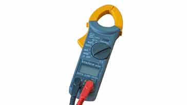
The toroidal transformer can be opened and closed around current carrying wires without the need to disconnect them. The clamp toroid acts as the transformer and is connected to the internal circuitry within the meter where the current is measured, and the reading is processed and displayed, typically on a digital readout.
These clamp meters often also have the more standard terminals for resistance and possibly even in circuit current measurements. But it is as a clamp current meter where this type of multimeter comes into its own.
Current transformer specifications
When selecting a current transformer there are many different specifications that need to be considered. In essence, many of these are exactly what might be expected, but there may be a few aspects that might need to be remembered.
There are many different specifications that can be applied to current transformers, and the ones below are some of the more important and widely used.
Type: It is important to select the type of transformer that is required. This will not only depend on the type of application, but also the current that it needs to monitor. Check that the type of transformer is suitable for the particular application. For example will it need to be added as a retro-fit, in which case it will need to be able to be clamped over the wire.
Current levels: The current levels for both the primary and secondary must also be specified. It is necessary that the primary can handle the current levels anticipated int he primary (with sufficient margin to accommodate over load) and the secondary must provide sufficient current to drive the ammeter of whatever form. The ratio is obviously dependent upon the turns ratio.
Frequency range: The frequency range of any transformer will be limited and obviously the same is true of a current transformer. Typically they are manufactured for small frequency ranges, often for power line / mains at 50 / 60 Hz, and some may be able to operate at frequencies up to 100 kHz or more. These ones would typically be used with switch mode power supplies. In any case the frequency range must be checked.
Ammeter load and performance: Often the output current of the current transformer will be specified for a given load. The meter used to measure the current should match this. Some current transformers are sold with integral current measuring device so the two electronic components are match and any inaccuracies removed.
Specifying the current transformer for the application for which it is intended is key to ensuring the electronic circuit will be able to operate in the manner expected.
Current sense transformers or current transformers are used in many areas of electrical electronic circuit design to provide current sensing in a variety of different situations. Not surprisingly there are many different types of these current transformers which are available in a variety of formats and sizes to suit a whole host of requirements. Accordingly these useful electronic components will almost certainly be available in the form that is required and with the specification that fits the bill.
 Written by Ian Poole .
Experienced electronics engineer and author.
More Test Topics:
Data network analyzer
Digital Multimeter
Frequency counter
Oscilloscope
Signal generators
Spectrum analyzer
LCR meter
Dip meter, GDO
Logic analyzer
RF power meter
RF signal generator
Logic probe
PAT testing & testers
Time domain reflectometer
Vector network analyzer
PXI
GPIB
Boundary scan / JTAG
Data acquisition
Return to Test menu . . .


