
Analogue Oscilloscope: cathode ray oscilloscope
Despite virtually all new scopes being digital, the analog or analogue oscilloscope, also called the cathode ray oscilloscope may still be found in many laboratories and other areas and is able to perform well .
Scope types includes:
Analogue scope
Analogue storage scope
Digital phosphor scope
Digital scope
USB / PC scope
Mixed Signal Oscilloscope MSO
Sampling scope
Oscilloscope Tutorial Includes:
Oscilloscope basics
Oscilloscope types
Specifications
USB vs bench-top scope
How to use an oscilloscope
Scope triggering
Oscilloscope probes
Oscilloscope probe specifications
Despite the take-over of digital technology, many analog or analogue oscilloscopes are still in everyday use providing excellent performance.
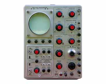
The analogue scopes are also often called cathode ray oscilloscopes and this can be abbreviated to CRO. These analog or cathode ray oscilloscopes may not have all the functionality of their digital cousins but they can still provide the capabilities required for most laboratory and general test applications.
Often analogue scopes may be put to one side in a stock of laboratory test equipment. However these test instruments can still be used to good effect in many situations, some people preferring to use them against more advanced digital scopes. In some instances analog scopes can still be bought new, although the number and selection of these test instruments is fast reducing.
Analogue scope basics
The key to the operation of an analog scope is its display. It uses the cathode ray tube or CRT. This form of display was for many years the only viable form of display that could be used to display images. Accordingly it was used in television sets for many years, although other forms of display including LCDs, LEDs and many other format are now used, but these all require digital signal inputs to the display.

The form of cathode ray tube used on oscilloscopes employed electrostatic rather than magnetic deflection of the electron stream. This provided much faster control of the electron stream, enabling analogue oscilloscopes to achieve very high frequency operation. The magnetic beam deflection scheme that was used in television sets did not provide sufficiently high frequency operation.
Looking at the operation of the analogue scope in more detail, it uses the cathode ray tube to display signals in both X (horizontal) and Y (vertical) axes. Typically the Y axis is the instantaneous value of the incoming voltage and the X axis is ramp waveform.
As the ramp waveform increases in voltage so the trace moves across the screen in a horizontal direction. When it reaches the end of the screen, the waveform returns to zero and the trace moves back to the beginning.

Using this approach it can be seen that as the X axis corresponds to time, and the Y axis to amplitude. In this way the familiar plots of waveforms can be displayed on the cathode ray tube.
Analogue oscilloscope operation
The analogue oscilloscope has a large number of circuit blocks and is able to provide stable images of incoming waveforms. The analogue scope was in use for many years and its circuitry was well tried and tested.
Looking in more detail at the internals of the analogue scope there are a variety of different circuit blocks that enable the operation to take place.
A more detailed block diagram of the scope can be seen in the diagram below.

- AC / DC selection In many instances signals will be superimposed in a DC bias. When looking at the signal, often only the AC elements will be of interest. In these cases, it is possible to place a capacitor in series with the input to ensure that the DC is blocked. This enables the signal amplifier to see greater detail without becoming overloaded by the DC content. As a capacitor is used, selecting the AC option will mean that low frequency signals may be limited. Check the scope specification for the low end performance.
- Y attenuator: In order to ensure that the signals are presented to the Y amplifier at the required level the signals pass into the Y attenuator.
- Y Amplifier: The basic Y amplifier provides the amplification to provide the output to the drivers froth e cathode ray tube. It is essential that this amplifier is particularly linear as this will determine the accuracy of the oscilloscope.
- Y deflection circuit: Once amplified the signal is passed to the Y deflection circuit. This uses the amplified signal and presents it to the plates of the cathode ray tube at the levels required. Electrostatic deflection is used on the CRT as this gives the high speed deflection that is needed for an oscilloscope.
- Trigger circuitry The trigger system consists of a number of blocks on the circuit diagram of the analogue scope. In order to ensure that a steady waveform is displayed on the display, it is necessary to set the ramp waveform to start at the same point on each cycle of the incoming signal to be monitored. In this way the same point on the waveform will be displayed at the same position on the display.
To achieve this the trigger circuit is used to start the ramp. The trigger picks off the signal from the incoming signal and when a particular voltage level is reached, it starts the ramp. This trigger point is adjustable on most oscilloscopes.
In terms of the analogue scope block diagram, a signal is taken from the output of the Y amplifier and fed into another conditioning amplifier. It is then passed through a Schmitt trigger circuit which provides single switch points as the waveform rises and falls. The required sense for the trigger is chosen so that the trigger point can occur on either the rising or falling edges of the waveform can be chosen before being applied to the ramp circuit, where the trigger signal provides the start point for the ramp.
It is also possible to use a signal from an external source. This can be a very convenient feature as it may be necessary to take the trigger from another source apart from the incoming signal. - Blanking amplifier A form of blanking is required to ensure that when the ramp or time-base circuit flies back to restart the trace again, it does not cause any illumination on the screen. In order to prevent this happening, a blanking amplifier is used to blank the screen during this fly-back phase. It simply takes the reset element of the ramp to generate a pulse that is applied to the grid of the cathode ray tube. This inhibits the electron flow and effectively blanks the screen for this period.
Analogue scope controls
There are very many controls on an analog oscilloscope to enable the test instrument to display the waveform in exactly the required manner.
Whilst most of the controls will be familiar to users of digital scopes a few may be rather different.
Some of the main controls are detailed below:
- Focus control: The focus control is not required on modern test instruments, but it was a key element of the older cathode ray oscilloscopes. The focus ensures that the dot that scans the screen remains as sharp as possible and in this way it can deliver a clear trace. It can be seen that as the control is adjusted, the dot or trace becomes better defined and less fuzzy.
- Intensity control: The intensity control is required on analog scopes because the intensity of the dot or trace varies according to the speed at which the scan is made. Controlling the intensity enables a clear trace of the required intensity to be obtained.
The intensity control may often be used because it is found that as the writing speed increases, the trace becomes steadily dimmer, and ultimately becomes difficult to see despite the intensity control. For higher frequency signals faster writing speeds are required, and as a result analogue oscilloscopes have a limited frequency range. Typically the maximum frequency that can be seen by an analogue oscilloscope is around 1 GHz. Above this other types of oscilloscope are required. - Signal inputs: There are a variety of controls associated wit the signal input or Y axis on the cathode ray oscilloscope.
- Vertical gain: The vertical gain control is the same on the cathode ray oscilloscope / analogue oscilloscope as it is on digital ones. It effectively varies the sensitivity, enabling the waveform to be expanded or contracted to fill the screen. Sometimes there may be a variable control to provide a limited amount of additional variation, but be aware the calibrations will not hold good if this is engaged. It is always best to leave this in the off position where the calibrations are correct.
- Vertical position: The vertical position control is used to bring the trace to the right portion of the screen.
- AC / DC / Gnd: This control is used to select the input coupling required on the scope. DC coupling will send the full DC voltage through to the Y amplifier input. Small variations in DC level may offset the trace, or if there is a high DC level it may not be possible to see the fine detail of the ripple ion a waveform if it has a high DC voltage. Selecting AC enables only the signal elements to be passed. Remember though that there will be a low frequency cut-off as it is capacitor coupled. On some scopes there may be a ground position as well.
- Timebase: One of the central controls on the oscilloscope will be the timebase control. This will have a wide variation in speed and will be calibrated in time per division on the scope cathode ray tube. This can range from very slow scans of a second or more per centimetre to microseconds and less per centimetre. It is necessary to choose the right timebase speed to display the particular waveform needed.
- Trigger: The trigger is one of the most central controls for the operation of the analogue oscilloscope. The trigger enables a stable signal to be seen on the screen. The controls are typically like those used on any form of oscilloscope, although naturally tailored for the operation and techniques used in analogue scopes.
- Trigger level: As might be expected, the trigger level sets the level at which the waveform starts, i.e. the trigger fires. In the case of an analogue oscilloscope it actually starts the ramp generator in the scope and as a result directly display the waveform seen from this point, unlike modern digital scopes that tend to capture the digital data and can process it accordingly, often having he “trigger” point in the middle of the screen.
- Hold-off: This control holds off retriggering for a short period. In this way it prevents retriggering too quickly and can enable some waveforms to be displayed in a more stable fashion, especially if the trigger level is exceeded more than once in the repetition of a complex waveform.
- Alt / Chop: This mode is present on dual or multiple channel scopes. When trying to display the waveform the cathode ray oscilloscope has two alternatives. One is to alternately display one waveform and then the next, or it can “chop” the signal, displaying a small bit of one signal and then a small bit of the second, etc. As the chopping rate is much above the signal frequency and therefore the waveforms appear as two separate signals. Often it is possible to see the chopping if the timebase is speeded up a lot.
These are several of the more widely used controls that appear on cathode ray oscilloscopes / analogue oscilloscopes. Other controls may be included, dependent upon the particular test instrument.
Analogue scope advantages and disadvantages
Despite the fact that technology has moved on and digital scopes are tending to dominate the market, there are still many areas where the analogue oscilloscope can provide very valuable service.
Advantages of using an analog oscilloscope or cathode ray oscilloscope:
- Cost: Analog scopes are generally much less expensive than their digital counterparts. The technology is well established and is therefore less expensive than leading edge technologies where large levels of development costs have to be recovered in addition to the component and production costs being higher
- Performance: Analog oscilloscopes are able to provide a good level of performance that is more than adequate for many laboratory and service situations.
- In company availability: It is often found that analog oscilloscopes may be available in an equipment store when all the other digital scopes are in use. Provided that their performance is satisfactory, the analogue option may provide an ideal way forwards.
Disadvantages of using an analog scope:
- High end performance: In view of the way in which they operate using analogue technology, these oscilloscopes are not able to provide all the capabilities of many of the high end digital oscilloscopes.
- Ranges available: In view of the bias towards digital oscilloscopes, oscilloscope manufacturers and suppliers have focussed on the newer digital scopes. Accordingly the ranges of analogue scopes available are much less than they were some years ago. Nevertheless some are still available new, and others from used test equipment suppliers. Often it is possible to pick up some very good deals from used test equipment suppliers, provided that approved or trustworthy suppliers are used and the proper safeguards are in place.
Despite its disadvantages and the fact that digital technology is taking over, analogue oscilloscopes or cathode ray oscilloscopes can still perform well. These test instruments may not have all the bells and whistles of a digital scope, but the older analogue versions can provide good reliable service.
Comparatively few analogue oscilloscopes are available for purchase new these days, but many are still available on the second user market, or these test instruments can be found in laboratories where they have not been superseded by newer models.
 Written by Ian Poole .
Experienced electronics engineer and author.
More Test Topics:
Data network analyzer
Digital Multimeter
Frequency counter
Oscilloscope
Signal generators
Spectrum analyzer
LCR meter
Dip meter, GDO
Logic analyzer
RF power meter
RF signal generator
Logic probe
PAT testing & testers
Time domain reflectometer
Vector network analyzer
PXI
GPIB
Boundary scan / JTAG
Data acquisition
Return to Test menu . . .


