What is a Mixed Signal Oscilloscope MSO
A Mixed Signal Oscilloscope, MSO is a type of oscilloscope that combines the normal analogue channels of an oscilloscope with additional logic channels of a logic analyzer.
Scope types includes:
Analogue scope
Analogue storage scope
Digital phosphor scope
Digital scope
USB / PC scope
Mixed Signal Oscilloscope MSO
Sampling scope
Oscilloscope Tutorial Includes:
Oscilloscope basics
Oscilloscope types
Specifications
USB vs bench-top scope
How to use an oscilloscope
Scope triggering
Oscilloscope probes
Oscilloscope probe specifications
Mixed signal oscilloscope, MSO are becoming increasingly popular as the need increases for combining the analogue measurement channels of an oscilloscope with the logic channels of a logic analyzer.
When investigating boards with logic elements such as embedded systems using an MCU or MPU, it is often necessary a way to combine the analogue channels of a traditional scope so that waveforms can be investigated at the same time as seeing the logic levels on other areas of the circuit. By combining all these elements together, investigating these circuits becomes easier.
Using a mixed signal oscilloscope, MSO, it is possible to undertake detailed investigations of these embedded systems far more easily. Whilst it would not be viable to have a 16 channel oscilloscope, it is quite possible to have, say, a two or 4 channel scope combined with a 16 channel logic analyzer function.
Why mixed signal oscilloscopes
The key advantage of an MSO, mixed signal oscilloscope is that it allows multiple time-aligned digital and analogue waveforms to be displayed on a single display. This can be key to enabling the operation of an embedded circuit to operation to be understood and investigated.
One of the key advantages of an MSO is that it can be used in almost the same way as a normal oscilloscope - the operation is relatively straightforward and easy. Most engineers and embedded system designers have a basic knowledge of how to use an oscilloscope. This can be compared to a full logic analyzer where the operation is different. Time may be needed to learn or relearn how to use a logic analyzer. As a result many design and test engineers often avoid using logic analyzers.
Another reason for the reluctance of many engineers to use logic analyzers is the time needed to set up and make measurements using logic analyzers.
Also the advanced techniques and capabilities available on a full logic analyzer may be way beyond what is needed for embedded systems with MCUs or even for investigating boards that use digital signal processing technology. Logic analyzers also typically provide many more logic channels - these may be needed in some applications, but often they may not be required.
As a result of these issues mixed signal oscilloscopes, MSOs, are often the preferred option. Their ease of use and the level of functionality they provide is more suited to these applications.
Waveform update is one of the important characteristics of an oscilloscope since it directly impacts the instrument’s usability. With sluggish response limiting the usability, users may find it frustrating to operate an unresponsive and slow oscilloscope. This applies not only to DSOs but to MSOs as well. Thus, oscilloscope vendors should ensure that waveform update rate is not compromised when they create an MSO by porting logic acquisition channels into a DSO. Otherwise, this would lead to sacrificing the use-model of traditional oscilloscope. Moreover, mixed-signal measurement solutions that are based on external logic pods and/or two-box solutions connected through an external communication bus like USB are generally difficult to use and unresponsive. On the other hand, MSOs that are based on highly integrated hardware architecture are easier to use and more responsive.
MSO capabilities
The aim of the mixed signal oscilloscope is to provide the functionality of a digital oscilloscope along with that of a basic logic analyser.
The logic analyser performance is normally not that of the top-line analysers, but will normally include 16 or 32 channels and functions such as parallel / serial bus protocols decoding and triggering.
The MSO scope channels operate in the same way as a traditional scope - the instrument can be used purely as an oscilloscope if required. The MSO treats the oscilloscope and logic channels in different ways:
- Oscilloscope channels: These are full analogue channels that use a analogue to digital converter, ADC, to convert the analogue inputs into a digital format. This information is then processed so that the waveform is displayed showing the analogue aspects of the signal
- Logic channels: The logic channels on the mixed signal oscilloscope are converted straight into a digital format. The signals then appear on the screen as a high or low level, and no analogue information is present. There are more of these logic channels to enable full visibility of the logic on a circuit, but they are much easier to implement because they do not require full analogue to digital conversion. If the analogue aspects of a digital signal are required to be viewed, then this can be connected to one of the analogue channels.
One of the key advantages of the Mixed Signal Oscilloscope, MSO is that only one unit is required for performing both oscilloscope and logic analyser based tests. When investigating logic circuits, particularly those using embedded software and using MCUs, often the full capability of a logic analyser is not needed. Instead an integrated combination of both scope and analyser is needed so that the analogue and digital traces are synchronised.
As such the MSO logic channels provide sufficient logic analysis for many applications, but combine this with an excellent oscilloscope to give a test instrument that is sufficient for most occasions.
Comparison of logic analyser and MSO
The MSO, mixed signal oscilloscope provides an excellent solution for many applications, but when choosing whether to proceed with one, there are some decisions to be made.
A comparison of typical capabilities is given below.
| Comparison of Logic Analyzer and Mixed Signal Oscilloscope |
||
|---|---|---|
| Parameter | Mixed Signal Oscilloscope | Logic Analyzer |
| Channel count | 16 / 32 | 64 to 204 + |
| Triggering | Single event on both analogue and digital channels | Advanced sequential capabilities |
| Timing analysis | Yes | Yes |
| State analysis | Yes: resulting from inclusion of separate channels for clocks | No; no provision for clock input |
MSO format
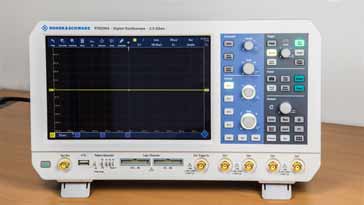
Mixed signal oscilloscopes can be obtained in a variety of formats. The traditional bench top box format is popular as many scopes use this format. Many oscilloscope manufacturers extend their ranges by adding the mixed signal capability into certain scopes within their ranges.
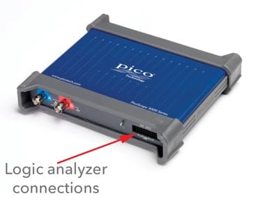
In addition to the bench top formats, USB PC based mixed signal oscilloscopes are also available. These typically have a maximum of 16 logic channels, but this may be added onto either two or four channel analogue channels making a very powerful instrument.
 Written by Ian Poole .
Experienced electronics engineer and author.
More Test Topics:
Data network analyzer
Digital Multimeter
Frequency counter
Oscilloscope
Signal generators
Spectrum analyzer
LCR meter
Dip meter, GDO
Logic analyzer
RF power meter
RF signal generator
Logic probe
PAT testing & testers
Time domain reflectometer
Vector network analyzer
PXI
GPIB
Boundary scan / JTAG
Data acquisition
Return to Test menu . . .