Beyond the Obvious: A Professional Approach to Systematic Fault Finding
Master professional fault-finding: learn to systematically isolate failures, trace signals, and diagnose failed components in electronic equipment.
Practical fault-finding includes:
How to debug a newly designed PCB / assembly
Fixing radios & other gadgets - first steps
Systematic fault finding
When fault finding a piece of electronic equipment, it's always best to check for any obvious issues first - it's surprising quite how many faults are easy to find.
But once all the obvious issues have been discounted, it is necessary to take a good look inside the equipment and tracing though the signal paths.
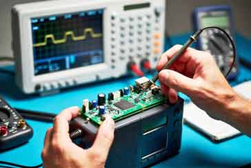
The equipment could range from domestic radios, to vintage radios, and test equipment to a host of other electronic gadgets and equipment found in the laboratory, workshop or even domestic equipment.
Fault finding is a discipline. It is a logical process of elimination that turns a mysterious, non-functional box into a series of predictable, measurable stages.
To succeed, you must move beyond guesswork and adopt a methodology that isolates the fault by tracing the signal path or analyzing the logical state of the circuit.
Fault finding is not guesswork, it is a form of detective work where logical tests are undertaken to steadily track down the area where the fault occurs.
The Philosophy of the "Divide and Conquer" Method
The most efficient way to troubleshoot any electronic device is to split the circuit into manageable sections.
If you try to look at the whole device at once, the complexity becomes overwhelming. Instead, by splitting the circuit down, it is possible to trace where the signal is present and correct, and where it is not.
Thee are logical stages to this approach.
Block Diagramming: Look at the service manual (or draw a simplified block diagram). Identify the main sections: power supply, input/signal processing, and output.
Isolate the Section: By measuring voltages or signals at the boundary of these blocks, you can quickly determine which section is failing. If the power supply is outputting the correct voltages but there is no sound at the output, you have already eliminated the power supply and narrowed the focus to the signal chain.
Progressive Tracking: Once you have isolated the faulty section, you can drill down into the specific components.
Signal Tracing: following the signal
Signal tracing is perhaps the most powerful tool in an electronics engineer's arsenal. It works on a simple principle: start at the input and follow the signal until it disappears.
It sounds simple, but its not always as easy as that, especially when there are loops int he circuit. But despite any difficulties, it is often the best way forward.
The Setup: Use an oscilloscope or a signal tracer (or even a simple high-impedance audio probe for low-frequency gear).
The Injection Method: If the device is silent, you can "inject" a known signal (like a 1kHz sine wave) into the input of a stage. You then probe the output of that stage. If the signal is present, that stage is likely functioning. Move to the next stage. If the signal vanishes, you have found the faulty stage.
Logic Method: In digital circuits or modern microcontrolled gear, signal tracing is about logic levels. Use a logic probe or a multimeter to check for clock pulses, data transitions, or "high/low" states. If a line is stuck at a steady voltage when it should be toggling, you have found your culprit.
Check the usual suspects
Once you have identified the faulty section through signal tracing, look at the bas levels and areas of the stage where the signal stops. Look for components that might not be working properly.
Over time, components tend to exhibit predictable failure modes. Here are some ideas of what to look for in the circuit.
• 1. Capacitor issues
Capacitors are arguably the most common points of failure in older equipment. Once you've isolated the problem circuit stage, it is worth taking a good look at the capacitors:
Electrolytic Capacitors: These contain a liquid electrolyte that dries out over time, especially if the device has been stored in a hot environment. As they dry, their capacitance drops, and their ESR (Equivalent Series Resistance) skyrockets, causing ripple, hum, or total failure.
Tantalum Capacitors: These are notorious for "shorting out" catastrophically. Unlike some electrolytics that just lose performance, a failed tantalum capacitor often becomes a dead short, which can drag down a power rail and lead to secondary damage of other components.
Paper/Wax Capacitors (Vintage Gear): In very old valve equipment, there may be very old paper-in-wax capacitors. Surprisingly these capacitors were used up until the mid-1950s in some equipment, the later ones being covered in a plastic outer layer. If they are pressent they are almost guaranteed to be "leaky." This does not mean they are leaking liquid; it means they are leaking DC current. If a capacitor is supposed to block DC between two stages, a leaky capacitor will pass that DC, upsetting the bias of the next valve or transistor and causing everything to operate in the wrong region of its characteristic curve.
• 2. Semiconductor degradation
We all expect transistors, FETs and the like to last forever, but this isn't always the case. There are times when these devices degrade over time.
Tin Whiskers: If you are working on 1960s-era radios, beware of germanium transistors in metal cans. These are prone to "whisker growth"—tiny, hair-like filaments of metal that grow inside the case, creating an internal short circuit between the leads. This is a classic, frustrating fault that can be hard to detect without removing the device and testing it out of circuit.
Thermal Fatigue: Semiconductors can also fail due to repeated thermal cycling, which eventually fractures the bond wires connecting the internal die to the external leads.
Other example of the finite life of semiconductor devices is Flash memory where the data can disappear over time - it may take many years, but the charge used to store the information can leak away over time.
Also LED lamps, particularly the ones used for lighting degraded with use and their light output diminishes. Although this is unlikely to be an issue in many standard electronic gadgets, it can be worth bearing in mind.
• 3. Valves & tubes
In many items of vintage equipment, valves or tubes are another suspect. They have a finite life. Cathode emission gradually falls off over time, leading to low gain or erratic performance. Sometimes, the heater itself may become open circuit.
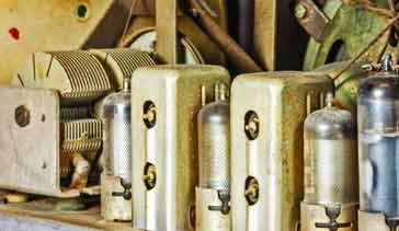
Always check the heater continuity first, and if you have a valve tester, verify the transconductance of the tube. Sometimes, if you have a spare, that can be dropped in temporarily to check whether it is the issue.
• 4. Resistance Drift
We often trust resistors and expect them to maintain their resistance pretty much exactly. Today's metal film resistors have an exceedingly high level of performance, but this wasn't always the case.
However, carbon composition resistors—common in equipment from the 1940s, 50s and 60s (and even before this) are hygroscopic. They absorb moisture from the air, and this is one of the causes of their resistance value drift over time - they usually drift higher in resistance over time. Heat is another issue that causes their resistance to change.
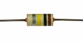
If you find a circuit where the voltages are significantly off, check the bias resistors. The resistance changes can be very significant, and obviously this can give rise toth e operating points of circuits changing significantly over time.
The Symptom of Overheating: Secondary Damage
When you find an overheated resistor or a scorched circuit board, do not replace the component and walk away. Overheating is rarely the primary fault; it is almost always a symptom of a fault elsewhere.
Ask yourself: What caused this component to run hot?
- Is there a short circuit downstream?
- Has a transistor failed in such a way that it is conducting excessive current?
- Is a filter capacitor drawing too much leakage current?
If you replace a burnt resistor without investigating the cause, the new resistor will simply burn out again. Always use your multimeter to check the resistance to ground of the downstream circuit before applying power to a new component.
Establishing a testing workflow
To keep your fault-finding logical, maintain a workspace workflow that prevents errors:
Documentation: Keep a notebook. Record the voltages you measure at each pin of a transistor or IC. Compare them to the service manual. If the manual says 5V and you have 0V, you know exactly where to trace back.
Safety First (Dim Bulb Tester): If you are working on mains-powered equipment, build a "Dim Bulb Tester." By placing an incandescent bulb in series with the device under test, you create a current limiter. If the device has a massive short circuit, the bulb will glow brightly, warning you to cut power before the electronics go up in smoke.
The "One Change" Rule: Never replace multiple components at once. If you suspect two capacitors are bad, replace one, test the device, and then replace the second. If you change five things and the device suddenly works (or breaks even further), you will never know which change was responsible.
Fault finding is a journey from the general to the specific - it's a bit like detective work. It requires patience, a systematic approach, and a healthy dose of suspicion toward the components that have stood the test of time.
By utilizing signal tracing to isolate the problem or problem area, understanding the typical failure modes of capacitors, resistors, and semiconductors, and refusing to treat symptoms as the primary disease, you can repair almost any electronic device.
The next time you sit down at the bench, don't just look for what is broken—look for where the signal stops, analyse the state of the circuit, and proceed with the steady, logical hand of an engineer. You are not just fixing a radio; you are unraveling a puzzle.
 Written by Ian Poole .
Experienced electronics engineer and author.
More Test Topics:
Data network analyzer
Digital Multimeter
Frequency counter
Oscilloscope
Signal generators
Spectrum analyzer
LCR meter
Dip meter, GDO
Logic analyzer
RF power meter
RF signal generator
Logic probe
PAT testing & testers
Time domain reflectometer
Vector network analyzer
PXI
GPIB
Boundary scan / JTAG
Data acquisition
Return to Test menu . . .