
USB Operation: Protocol, Data Transfer & Packets
USB, Universal Serial Bus has a defined protocol for the data transfer using a variety of specific types of data packets for its operation.
USB Universal Serial Bus Includes:
USB introduction
USB standards
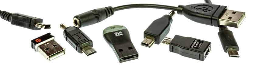
Connectors, pinouts & cables
USB-A connector colour codes
Data transfer & protocol
USB 3
USB-C
USB-C icons and performance indications
USB hubs
How to buy best USB hub
USB, Universal Serial Bus is very easy to use providing a reliable and effective means of transferring data and it is used in many areas from small memory sticks, to external hard drives, printers and many more peripherals.
Whether USB 1, USB 2, USB 3 or even USB 4, the data requires a standardised method of transfer over the USB interface along with a standard format for the USB data packets.
To achieve this the system has a defined the USB data transfer protocol, data packet format, etc that enables the data to be formatted and carried in a defined way that provides the reliable communication.
The bus also operates in a particular way, seeing the various devices attached to it independently of the actual physical layout of the system.
Although some changes have been made between the different updates to the USB standard as it progressed from USB 1 to USB 2, USB 3, and USB 4, the basic operation, protocol, signalling and data transfer modes, data packet format, etc are basically the same.
USB operational basics
In order to understand how the data transfers and the protocol operates within the USB environment, it is first necessary to understand how USB is physically set up and how it appears to the system / host.
For most systems using USB, the host will be some form of computer: desktop, laptop, tablet, etc, although this does not always need to be the case.
Although there is a lot of variation in the way a USB system may appear to be set up, essentially the same structure will be used and this reflects in the way it operates.
In terms of the definitions of the entities in a USB network, there are three main elements:
Host: The host is the computer or item that acts as the main element or controller for the USB system. The host has a hub contained within it and this is called the Root Hub.
Hub: The hub is a device that effectively expands the number of ports available - it will have one connection to the upstream connection, and several downstream. It is possible to plug one hub into another to expand the capability and connectivity further.
Port: This is the socket through which access to the USB network is gained. It can be on a host, or a hub.
Function: These are the peripherals or items to which the USB link is connected. Mice, keyboards, Flash memories, etc, etc.
Device: This term is collectively used for hubs and functions.
The physical layout of a USB 'network' may consist of the host with two (for example) ports and each of these may have a hub attached, to which further devices or 'functions' are attached.
The actual physical layout of the USB system will vary according to the actual situation, but the operation is always basically the same.
In terms of the data flow, the signals travel along the bus so that it is accessibly by all the functions, but only the destination function accepts it.

Selecting USB function destination
With data for all devices beings ent along the bus, it is necessary for the USB operation that the data is only accepted by the required function.
To achieve this, when a device is attached to the bus it is assigned a unique number or address by the host for the time it is connected.
In addition to the address, the device also contains endpoints. These are the actual sources and destinations for communications between the host and the device.
Endpoints can only operate in one direction, i.e. input or output, but not both, and devices can have up to 16, of which one each for the input and output must be reserved as the 'Zero Endpoint' for that direction. Although each device can have sixteen input and sixteen output endpoints, it is very rare for them all to be used.
The zero endpoints are used for a variety of activities including auto-detection and configuration of the device on the bus and the two zero endpoints are the only ones accessible until the device is properly connected on the bus.
USB data pipes
The communication within USB is based around the concept of using data pipes. These can be considered as being logical channels within the data flow on the bus.
In reality, a USB data pipe is a connection from the host controller to a logical entity within a device, i.e. the endpoint. Because pipes correspond to endpoints, the terms are sometimes used interchangeably.

The host then uses the concept of a data pipe to ensure the data to and from a device is correctly directed or the source is known. The data pipe uses a combination of the address, endpoint and also the direction to define it.
To communicate with the zero endpoints a special form of data pipe is needed because it needs to be used to establish the initial communication. It is called the Default Control Pipe and it can be used when the initial physical connection is made.
There are two types of USB pipe:
- Message Pipe : This type is a bi-directional USB pipe and it is used for control data. Message pipes are typically used for short, simple commands to the device, and for status responses from the device. They can be used by the bus control pipe number 0.
- Stream Pipe: This form of USB pipe is uni-directional and it is connected to a uni-directional endpoint that transfers data using an isochronous, interrupt, or bulk transfers (see below).
USB signalling and data transfer basics
For USB 1 and 2 a four wire system is employed. As detailed elsewhere, the cables carry: power, ground and then there is a twisted pair for the differential data transfer.
The lines are designated Data+, D+ and Data-, D- for USB 1 and USB 2. For USB 3, new lines were introduced. For each port there are TX1+ & TX1- and TX2+ & TX2- to cover the transmitted data and then for the received data the lines are RX1+ & RX1- and RX2+ & RX2-.
The use of twisted pairs and differential signalling reduces the effects of external interference that may picked up. It also reduces the effect of any hum loops, etc that could cause issues. As it is not related to ground, but the difference between the two lines, the effects of hum are significantly reduced
The data uses an NRZI system, i.e. non-return to zero.In terms of operation, when the USB host powers up, it polls each of the slave devices in turn.
The USB host has address 0, and then assigns addresses to each device as well as discovering the slave device capabilities in a process called enumeration. [Enumeration takes place when a new device is connected].
Transactions between the host and device comprise a number of packets. As there are several different types of data that can be sent, a token indicating the type is required, and sometimes an acknowledgement is also returned.
Each packet that is sent is preceded by a sync field and followed by an end of packet marker. This defines the start and end of the packet and also enables the receiving node to synchronise properly so that the various date elements fall into place.
There are four basic types of data transaction that can be made within USB.
- Control: This type of data transaction within the overall USB protocol is used by the host to send commands or query parameters. The packet lengths are defined within the protocol as 8 bytes for Low speed, 8-64 bytes for Full, and 64 bytes for High Speed devices.
- Interrupt: The USB protocol defines an interrupt message. This is often used by devices sending small amounts of data, e.g. mice or keyboards. It is a polled message from the host which has to request specific data of the remote device
- Bulk: This USB protocol message is used by devices like printers for which much larger amounts of data are required. In this form of data transfer, variable length blocks of data are sent or requested by the Host. The maximum length is 64-byte for full speed Devices or 512 bytes for high speed ones. The data integrity is verified using cyclic redundancy checking, CRC and an acknowledgement is sent. This USB data transfer mechanism is not used by time critical peripherals because it utilises bandwidth not used by the other mechanisms.
- Isochronous: This form of data transfer is used to stream real time data and is used for applications like live audio channels, etc. It does not use and data checking, as there is not time to resend any data packets with errors - lost data can be accommodated better than the delays incurred by resending data. Packet sizes can be up to 1024 bytes.
The data transfer methodology and protocol for USB provides an effective method of transferring the data across the interface in an effective and reliable manner.
USB data packets
Within the USB system, there are four different types of data packets each used for different types of data transfer.
Token Packets: Essentially a Token USB data packet indicates the type of transaction is to follow.
Data Packets: The USB data packets carry the payload data, carrying the data as required.
Handshake Packets: The handshake packets are used acknowledging data packets received or for reporting errors, etc.
Start of Frame Packets: The Start of Frame packets used to indicate the start of a new frame of data.
Although USB has developed from USB 1 through USB 2 to USB 3 and now USB 4, it still utilises the same basic approach to data transfer. There are many USB connectors and leads available, and these leads now have many more wires for higher rate data transfer. Accordingly the data transfer speeds have increased many fold over the first USB specification that was released and the devices that were available.
 Written by Ian Poole .
Experienced electronics engineer and author.
Wireless & Wired Connectivity Topics:
Mobile Communications basics
2G GSM
3G UMTS
4G LTE
5G
Wi-Fi
Bluetooth
IEEE 802.15.4
DECT cordless phones
Networking fundamentals
What is the Cloud
Ethernet
Serial data
USB
LoRa
VoIP
SDN
NFV
SD-WAN
Return to Wireless & Wired Connectivity


