Programmable Unijunction Transistor, PUT
The programmable unijunction transistor, PUT, was a later development of the unijunction concept that enabled the trigger voltage to be set and other improvements gained.
Unijunction Transistor Includes:
What are unijunction transistors & their types
Traditional diodic unijunction transistor, DUJ
Programmable unijunction transistors, PUTs
A programmable unijunction transistor or PUT is a semiconductor device that builds on the original diodic type of unijunction transistor.
The PUT has many similarities, but also some significant differences, enabling it to be used in a larger number of applications.
Although the programmable unijunction transistor has the term programmable in its title, it is not programmable in terms of using software, etc, but instead the trigger points can be set using external resistors.
The name for the device was created in the 1950s after the device was first invented, and the term programmable had very different meaning then.
the programmable unijunction has two other types of device with which it competes and against which it is often compared. These are the original or diodic unijunction transistor, and the thyristor of silicon controlled rectifier.
Differences between Diodic and programmable unijunction transistors
The diodic unijunction transistor, DUJ was the first type of unijunction to be developed. It was used in many early circuit designs, and even now when unijunction transistors are mentioned, it is the original type that is used as can be seen from the circuit symbol used.
This form of unijunction uses a single bar of the silicon, and one PN junction is fabricated into this. It gives its
The programmable unijunction transistor was developed later by General Electric in the early 1960s as a better alternative to the original type.
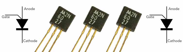
The first indication of their differences can be seen by the circuit symbols. The diodic unijunction looks more akin to a junction FET albeit with the emitter connection angled onto the channel element. The programmable unijunction has a circuit symbol that looks more like a thyristor.

Another key difference is the fact that the diodic component has just a single junction, whereas the programmable one has an internal structure more like a thyristor.
Also the trigger voltage of the diodic unijunction is determined solely byt he device itself, whereas the programmable one - giving its name to the device - is determined by the values of two external resistors
PUT vs SCR / Thyristor
Programmable unijunction transistors are very similar to the more familiar thyristors, often referred to as silicon controlled rectifiers, or SCRs.
The structure is very similar and their mode of operation is also very similar as they are both semiconductor devices that can be used to control currents. However, there are also several differences
Triggering: A programmable unijunction transistor or PUT, on the other hand, can be triggered by a voltage applied to its gate terminal. The most commonly used method for triggering a thyristor is by a small pulse of current applied to its gate terminal. This makes PUTs more versatile than thyristors, as they can be triggered by a variety of different signals
ON-state resistance: The ON-state resistance of a unijunction transistor is generally much lower than that of a thyristor.
Switching speed: The switching speed of a programmable unijunction transistor, PUT is generally much faster than that of a thyristor, and this can be very helpful, especially in some control applications.
Applications: In view of their overall performance, the two types of electronic component tend to be used in different arenas where the best use can be made of their performance. Unijunctions tend to be used more for timing and oscillator circuits, whereas thyristors tend to be used for power control circuit designs.
Often programmable unijunction transistors are a better choice than thyristors where fast switching speed is important. Thyristors are generally chosen where high current and voltage handling are important.
| Comparison Summary of Programmable Unijunction Transistors, UJTs and Thyristors |
||
|---|---|---|
| Parameter | Programmable Unijunction Transistor, PUT | Thyristor (SCR) |
| Triggering | Voltage | Current |
| On-state resistance | Low | Higher |
| Switching speed | Fast | Slower |
| Typical applications | Timing, oscillators, thyristor driver | Power control |
Structure of a programmable unijunction transistor, PUT
Although the programmable unijunction transistor is more complicated than the basic diodic unijucntion, it is nevertheless a relatively easy device to fabricate.
The PUT consists of four layers, alternating p-type and n-type regions in approximately equal proportions.
The device looks very similar to that of a thyristor in its construction, but the difference is that the gate electrode is connected to the n-type region next to the p-type anode layer.

In addition to the basic semiconductor construction of the device, ohmic contacts are made on the anode, cathode and gate layers so that the external connections can be provided.
.PUT characteristics
One of the main characteristics that is of importance with the programable unijunction transistor is the anode voltage vs anode current.
When looking at this, it should be remembered that for most electronic circuit designs, the anode is connected tot he rail voltage and the cathode will be connected to ground. The gate will be connected to the two external "programming" resistors which set the trigger voltage or to be more exact the standoff ratio, η and the peak voltage Vp shown in the diagram.

With the PUT unijunction, it is found that as the anode to cathode voltage is increased so the anode current increases initially.
However, the anode voltage cannot increase beyond a certain point and here it is found that the number of charges that are injected cannot increase because of charge saturation.
This means that the anode voltage actually decreases giving rise to a negative resistance region in the characteristic curve.
The anode voltage continues to fall until it reaches a minimum where no more decrease in anode voltage is possible because there is full saturation of the charges.
After the minimum, which is also known as the valley point, the anode voltage again starts to rise and it behaves like a typical PN junction diode.
The negative resistance region can be particularly useful, especially in relaxation oscillator circuit designs.
It is also worth noting the peak voltage, Vp which is the anode to cathode voltage after which the PUT characteristic moves into a negative resistance region. It normally occurs at a point which is equal to the voltage of one forward biased N junction diode (0.7V) plus the gate to cathode voltage, Vg.
Programmable unijunction device circuit key calculations
There are a few parameters that are used within programmable unijunction circuits and these relate to the trigger voltage.
The first is the calculation of a value referred to as Eta η and this is the voltage set on the gate of the device, and it is also called the intrinsic standoff ratio..
To calculate the peak voltage, Vp, the following formula can be used.
Basic PUT unijunction circuit
One of the msot basic circuits for any unijunction, whether it is a diodic or programmable form is the simple relaxation oscillator.
The circuit using a diodic unijunction is simpler than the one for the programmable unijunction because this one requires additional resistors to set or "programme" the trigger voltage.

Within the relaxation oscillator, the resistors R1 and R2 set the peak voltage and the intrinsic standoff ratio η.
The resistor R3 limits the cathode current whilst R3 and C1 set the frequency of the oscillator.
The output from the oscillator can be taken from the junction of R3 and C1, and this means that any loading will alter the frequency of the oscillator. If this is to be required for a reasonably accurate timing or frequency function, then a circuit like an emitter follower or source follower would be advised to provide a high impedance load.
Another alternative is to take the output from the cathode of the unijunction and this will load the circuit much less, although the waveform will be different.
The programmable unijunction transistor is the type that is more widely available these days. It does required additional electronic components for simple circuits like the relaxation oscillator, but it is a far better option in terms of performance than the old diodic unijunctions that became popular at one stage.
 Written by Ian Poole .
Experienced electronics engineer and author.
More Electronic Components:
Batteries
Capacitors
Connectors
ADC
DAC
Diodes
FET
Inductors
Memory types
Phototransistor
Quartz crystals
Relays
Resistors
RF connectors
Switches
Surface mount technology
Thyristor
Transformers
Transistor
Unijunction
Valves / Tubes
Return to Components menu . . .