
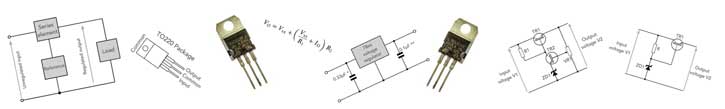
Linear Voltage Regulator Circuit Design: series pass regulators
There are many series linear voltage regulator circuits using simple one transistor designs upwards to more complex IC based regulators.
Linear Power Supply Circuits Primer & Tutorial Includes:
Linear power supply
Shunt regulator
Series regulator
Current limiter
Constant current vs foldback limiting
78** series regulators & circuits
LM317 voltage regulator & circuits
LDO, low dropout regulators
See also:
Power supply electronics overview
Switch mode power supply
Capacitor smoothing
Over-voltage protection
PSU specs
Digital Power
Power management bus: PMbus
Uninterruptible power supply
The series voltage regulator or as it is sometimes called the series pass regulator is the most commonly used circuit design approach for providing the final voltage regulation in a linear regulated power supply.
The series linear voltage regulator provides a high level of performance, especially when low noise, ripple and transients are required in the regulated output and the circuits are often relatively easy to design.
There is a good variety of linear voltage regulator circuits using discrete electronics components that provide regulation with a series pass element - the series pass technique is that which is most widely used in power supply units.
This means that there are many options for series voltage regulators that are open when undertaking the electronic circuit design of a power supply.
It is possible to one of the many voltage regulator ICs or chips to be used in the circuit design. These ICs are widely available and they are also quite cheap making them an ideal option for many linear voltage regulator circuits.
Series voltage regulator circuit basics
The series voltage regulator or series pass voltage regulator uses a variable element placed in series with the load. By changing the resistance of the series element, the voltage dropped across it can be varied to ensure that the voltage across the load remains constant.

The advantage of the series voltage regulator is that the amount of current drawn is effectively that used by the load, although some will be consumed by any circuitry associated with the regulator.
Unlike the shunt voltage regulator, the series regulator does not draw the full current even when the load does not require any current. As a result the series voltage regulator is considerably more efficient.
Instead of drawing the current not required by the load to maintain the voltage, it drops the voltage difference between the input voltage and the required stabilised voltage.
To maintain a sufficient level of regulation and rejection of noise and transients that may be on the incoming voltage, series linear voltage regulators need to drop a significant voltage.
Many high quality, low noise and ripple voltage regulators need several volts across the series regulator element. This means that significant levels of power many be dissipated in this component, and good heat sink and heat removal capability is required for the series pass regulator device and also the power supply as a whole.
Even though a series regulator is considerably more efficient than a shunt regulator, it is considerably less efficient than a switch mode power supply.
The efficiency of a series voltage regulator and any linear power supplies using them will depend on the load, etc, but often efficiency levels of less than 50% are achieved, whereas switch mode power supplies can achieve levels greater than 90%.
Series voltage regulators have relatively low levels of efficiency when compared to a switch mode power supply, but they have the advantages of simplicity and also their output is free of the switching spikes seen on some switch mode supplies, although SMPSs are improving and the performance of many is exceptionally good nowadays.
Simple emitter follower voltage regulator
The electronic circuit design for a simple transistor emitter follower voltage regulator is very straightforward. This circuit is not widely used on its own in a linear power supply, but may be used within other equipment to provide a step down voltage, etc from a higher voltage rail.

The circuit uses a single pass transistor in the form of an emitter follower configuration, and a single Zener diode or other voltage regulator diode driven by a resistor from the unregulated supply.
This provides a simple form of feedback system to ensure the Zener voltage is maintained at the output, albeit with a voltage reduction equal to the base emitter junction voltage - 0.6 volts for a silicon transistor.
It is a simple matter to design a series pass voltage regulator circuit like this. Knowing the maximum current required by the load, it is possible to calculate the maximum emitter current. This is achieved by dividing the load current, i.e. transistor emitter current by the β or hfe of the transistor.
The Zener diode will generally need a minimum of around 10mA for a small Zener to keep its regulated voltage. The resistor should then be calculated to provide the base drive current and the minimum Zener current from a knowledge of the unregulated voltage, Zener voltage and the current required. [ (Unregulated voltage - Zener voltage ) / current ].
it is worth noting that a small margin should be added to the current to ensure that there is sufficient room for margin when the load, and hence the transistor base is taking the full current.
The power dissipation capacity for the Zener diode should be calculated for the case when the load current, and hence the base current is zero. In this case the Zener diode will need to take the full current passed by the series resistor.
Sometimes a capacitor may be placed across the Zener diode or voltage reference diode to help remove noise and any voltage transients that may occur.
Ideas for your projects . . . . . .
This great value equipment has been selected for your interest and it is available via AliExpress. Alternatively check out my Amazon .com Storefront.

Linear Voltage Regulators Kit: LM317, 7805, 7812, etc
This kit contains a total of 50 TO220 package voltage regulator ICs which include: LM317T L7805CV L7806CV L7808CV L7809CV L7810CV L7812CV L7815CV L7818CV L7824CV

LM317 Adjustable Regulator Kit
Based around the reliable LM317 regulator chip, this kit contains all the components to make a continuously adjustable DC regulator 1.5V - 12V - ideal for teaching & training. Requires a DC smoothed input.

0-30V 2mA-3A DC Regulator Kit
This regulator provides a great way of creating a variable output voltage from a DC smoothed supply. For higher current levels it will require an additional heatsink for the pass device, otherwise it receives good reviews.
. More Linear Regulators . . .
More convenient to buy from Amazon.com?
Note: We make a small commission from any sales at no cost to you.
Output sampling
The simple emitter follower series voltage regulator circuit directly compared the output with the voltage reference. In this way the output voltage was equal to that of the reference, neglecting the base emitter voltage drop.
However it is possible to improve the performance of the voltage regulator by sampling a proportion of the output voltage and comparing it to the reference.
A differential amplifier like an operational amplifier can be used for this function. If this is done, then the output voltage becomes greater than the reference voltage as the negative feedback in the circuit fights to keep the two compared voltages the same.
If for example the reference voltage is 5 volts and the sampling or potential divider provides 50% of the output voltage, then the output voltage will be maintained at 10 volts.

The potential division or sampling can be made variable, and in this way, the output voltage can be adjusted to the required value. Normally this method is only used for small adjustments as the minimum output level obtained by this method is an output equal to the reference voltage.
It should be remembered that using a potential divider has the effect of reducing the feedback loop gain. This has the effect of reducing the loop gain and thereby reducing the regulation performance. Normally there is sufficient loop gain for this not to be a major problem except when only a very small proportion of the output is sampled.
Care should also be taken not to increase the voltage of the output to a point where the regulator does not have sufficient drop across it to regulate the output voltage sufficiently.
Series pass regulator with feedback
In order to provide improved levels of performance over that provided by a simple emitter follower, it is possible to add a more sophisticated feedback network into the voltage regulator circuit. This is achieved by sampling the output, comparing it to a reference and then using some form of differential amplifier to feedback the difference to correct the errors.
It is possible to use a simple two transistor circuit for a series pass regulator with voltage sensing and feedback. Although it is quite straightforward to use an operational amplifier, which will provide higher levels of feedback, and hence better regulation, this two transistor circuit illustrates the principles well.

In this circuit TR1 forms the series pass transistor. The second transistor, TR2 acts as the differential amplifier, feeding the error voltage between the reference diode and the sensed output voltage which is a proportion of the output voltage as set by the potentiometer. The resistor, R1 provides the current for the collector of TR2 and the voltage reference diode ZD1.
Voltage reference
Any linear voltage regulator can only be as good as the voltage reference that is used as the basis of the comparison within the system.
While a battery could in theory be used, this is not satisfactory for most applications. Instead Zener diode based references are almost universally used.
Integrated circuit regulators and references use sophisticated on-chip combinations of transistors and resistors to obtain temperature compensated and precise voltage reference sources.
The voltage reference must be driven from the unregulated supply. It cannot be taken from the regulated output as there are start-up issues. At start-up there is no output and therefore the reference output will be zero and this will be maintained until the reference starts-up.

Interestingly, it will be seen that the basic Zener diode style basic voltage reference is a shunt regulator and not a series regulator. However this voltage reference is then used to drive the series voltage regulator circuit.
Often the output from the reference source is fed via a potential divider. Not only does this reduce the output voltage which is normally very useful, but it also allows a capacitor to be added to the output to help remove any ripple or noise that may be present. The reduced voltage is also useful because the minimum voltage output is governed by the reference voltage.
Integrated circuit linear voltage regulators
There are very many excellent integrated circuits that enable a series regulator to be designed very easily. Many of them have been around for several years and as a result they are widely available and very cheap.
Integrated circuits such as the famous 78xx series, LM317, LM340 series and many others provide a very easy way of creating a simple yet very good linear regulator.
These particular circuits are three terminal regulators having one terminal for the input, one for the output and a common, either taken to earth or to a resistor network for the voltage feedback.
• 74xx series & LM340 series regulator circuits
The 78xx series of regulators are very well known and have been available for very many years. They are available ina wide variety of voltages, the "xx" being replaced by the voltage required.
These regulators are simple three terminal devices, but they have a large number of incorporated capabilities apart from just the voltage regulation: internal current-limiting, thermal shutdown and safe-area compensation, making them almost indestructible.

This voltage regulator circuit is very straightforward and uses very few electronic components.

This is the basic circuit used for any 7800 series voltage regulator. It is very successful and requires no additional components beyond those shown for the basic operation.
The LM340 series are virtually the same as the 78xx series except that they have a slightly higher specification, and closer tolerance on the output voltage.
• LM317 regulator circuits
The LM317 voltage regulator IC is an adjustable 3−terminal positive voltage regulator capable of being used in circuit designs that can supply in excess of 1.5 A over an output voltage range of 1.2 V to 37 V.
This assumes that the input voltage is such that a sufficient voltage drop between the input and output can be gained to give sufficient regulation at the output voltage required.
The LM317 provides the basic electronic component to create a very simple, and yet effective variable voltage regulator circuit design. The design is very easy and requires two external resistors to enable the output voltage to be set.
In addition to this the IC incorporates internal current limiting, thermal shutdown and safe area compensation, making it very reliable and almost difficult to damage.
In view of the way in which the output voltage can be set using two external resistors, voltage regulator circuit designs can be made to have programmable output regulator or by connecting a fixed resistor between the adjustment and output, the LM317 can be used as a precision current regulator.

Low drop out series voltage regulators
One of the considerations of any regulator is the voltage that must be placed across the series pass element. Often for linear regulators a significant drop across the series pass element is required to achieve the best regulation and noise rejection. For example a linear regulator with an output of 12 volts may be designed to have an input voltage of 18 volts or more.
With any linear regulator there is a minimum voltage that is required across the series element before the regulator "drops out." This drop out voltage may be seen in many linear regulator integrated circuits.
In some circuits, having a low drop out regulator is important. If the input voltage available is not particularly high, having a low drop out linear regulator can be important. It will need to regulate well, despite having a limited voltage across it.
Key parameters for series linear voltage regulators
When looking at the specifications for series linear regulators, or when undertaking the electronic circuit design for one, there are a number of parameters that are of great importance
Maximum input voltage: This is the maximum input voltage that the series regulator can withstand. Often having a good voltage drop across the regulator will ensure better regulation. However the maximum input voltage must not be exceeded and normally it is good practice to have a significant margin between the voltage applied and the specified maximum. Running at 60% or less is normally good practice and will improve the reliability.
Input voltage-output voltage differential: The maximum input output differential is another figure of importance and it represents the voltage across the series pass element. In some cases the regulator chip itself may operate above ground, and in this case the maximum input output voltage is of great importance. Again, running well below the maximum will ensure greater reliability.
Current rating: Any linear voltage regulator will have a maximu current it can pass. The higher the current the higher the power dissipated, especially for large voltage drops across the series regulator element. The maximu current specification will depend on a variety of factors including the level of heat-sinking for the regulator element as well as the ambient temperature in the equipment and of course the voltage differential.
Drop out voltage : The drop out voltage specification represents the minimum input-output voltage differential across the series regulator where it can provide a regulated output. For many regulators it can be several volts, but for low drop-out regulators it can of the order of a few hundred millivolts.
Line regulation: The line regulation os the variation in output for a given variation in the input voltage. To ensure good line regulation, there should be sufficient voltage drop acros the regulator, and also sufficient gain in the feedback and voltage sensing loop.
Load regulation: The load regulation is variation in output voltage for a given change in the load, and hence the current drawn. Again, good feedback in the voltage sense loop, but the current carrying wires should also be sufficient to carry the current without a noticeable voltage drop. Sometimes electronic circuit designs will sense the voltage actually at the load to remove the effects of the voltage drop along the wires. It is also necessary to ensure the supply toth e regulator can handle the required curent levels.
Find out Voltage Regulator Data:
Check out the data for a large variety of voltage regulators along with the distributor stock levels and prices.
Find out more about Voltage Regulator Chips & Data
Hints and tips for voltage regulator circuit design
There are several useful hints and tips that can be followed to help ensure that a design for a linear voltage regulator will perform to its expectations.
Device dissipation: Series regulators can dissipate large amonts of heat. Accordingly it is necessary to ensure that the series regulator device can handle the power and in addition to this that it is provided with sufficient heatsinking capability, how ever this may be arranged.
It is also necessary to ensure that the temperature rise in the overall power supply does not rise to high as a result of the heat dissipated as this may impact the reliability. Electrolytic capacitors in particular degrade faster if they run in a hot environment.
Is series regulator voltage drop sufficient: In order to have good regulation, there must be a sufficient voltage drop across the regulator transistor, FET, or IC. The minimum drop will be quoted for voltage regulator ICs in their data sheets.
Is the input decoupled sufficiently: In some instances, where there may be longer wire lengths to a regulator IC, a small decoupling capacitor from the input to ground is advised. If this is not in place, the IC can oscillate.
Is there sufficient capacitance on the output: To improve the transient response of a regulator, a capacitor can be placed across the output. This may typically be of the order of 0.1µF to 1µF dependent upon the circuit. If a voltage regulator IC is used as the basis of the voltage regulator circuit, then optimum values will be suggested in the datasheet.
Are the tracks and wires sufficient for the current: It is very convenient to use small tracks in a printed circuit board to ensure that all the electronic components and the linking circuitry can be contained on the board. However, where higher current levels may be experienced it is essential to make sure that any tracks can carry the current without dissipating too much heat or dropping the voltage.
The same is also true if ordinary wiring is used - thin wires can drop the voltages in just the same way as think tracks on a printed circuit board.
Can the input circuitry and smoothing supply sufficient current: Prior to the linear voltage regulator circuit itself, the smoothing circuit provides an essential element of the overall supply. This must be capable of providing the required current without the voltage dropping too low. Also the ripple will increase as more current is drawn.
It is essential to ensure that at all times, the minimum voltage is at all times sufficient to operate the regulator - soemtimes the troughs in the ripple could fall below the minimum for the regulator to operate satisfactorily. These factors must be borne in mind when designing the voltage regulator circuit.
Is current limit incorporated: Current limiting is an essential element of modern voltage regulator circuits and one should be incorporated if possible. Most voltage regulator ICs incorporate curent limiting, but circuits using discrete components will need to have this capability designed in.
Having a current limit capability will prevent damage to the power supply itself and also the load being driven should a short circuit or other overload condition occur.
Is over-voltage protection incorporated: There can be some instances where the regulator could fail and the full input voltage to the regulator could be placed across the load. This could result in damage to the circuit being driven. Having over-voltage protection could save significant damage being done to the electronic circuit being powered.
These are just a few of the design precautions that need to be considered when designing or constructing a linear regulator circuit for a power supply. They are normally easy to overcome, and they can act as a design checklist and can even be added to.
While the circuits shown here are simple transistor circuits, the same principles are used in larger circuits and also within integrated circuits. The same series pass regulator concepts as well as the reference diode circuits, sampling and other areas all use the same elements.
The concepts used here are used within virtually a linear regulated power supplies which can offer very good levels of performance. The linear regulated power supplies are larger and heavier than switch mode power supplies, however they have a name for low noise and good regulation on the output, free from the spikes that some switch mode power supplies have.
 Written by Ian Poole .
Experienced electronics engineer and author.
More Circuits & Circuit Design:
Op Amp basics
Op Amp circuits
Power supply circuits
Transistor design
Transistor Darlington
Transistor circuits
FET circuits
Circuit symbols
Return to Circuit Design menu . . .


